•
Rear dual PSU power slots with front-to-back or back-to-front airflow
•
One rear slot for fan module with front-to-back or back-to-front airflow
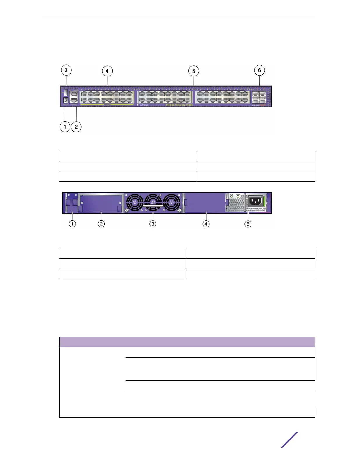
Figure 65: X460-G2-16mp-32p-10GE4 Front Panel
1 = USB port 4 = PoE+ 100/1000/2.5G BASE-T ports
2 = Stack number indicator 5 = PoE+ 10/100/1000BASE-T ports
3 = Console port/Ethernet management port 6 = SFP+ 10GBASE-X ports
Figure 66: X460-G2-16mp-32p-10GE4 Rear Panel
1 = TM-CLK (clock) slot cover
4 = Blank power supply cover
2 = VIM slot cover 5 = Power supply slot
3 = Fan module slot
ExtremeSwitching X460-G2 Series Switch LEDs
Table 10 describes the meanings of the front-panel LEDs on all X460-G2 series switches.
Table 10: X460-G2 Front Panel LEDs
Label or Type Color/State Meaning
M (Management) Slow blinking green (1 Hz) Normal operation
Fast blinking green (2 Hz) Power-on self test (POST) in progress
or
Switch diagnostics are running
Steady green POST passed; system is booting image
Blinking amber System is disabled: POST failed or system
overheated
O No external power is attached
ExtremeSwitching Switches
ExtremeSwitching and Summit Switches: Hardware Installation Guide 55
 Loading...


