Installation: Labeling, Cabling, Mounting, cont’d
MLC 226 Series • Installation: Labeling, Cabling, Mounting2-10
PRELIMINARY
5
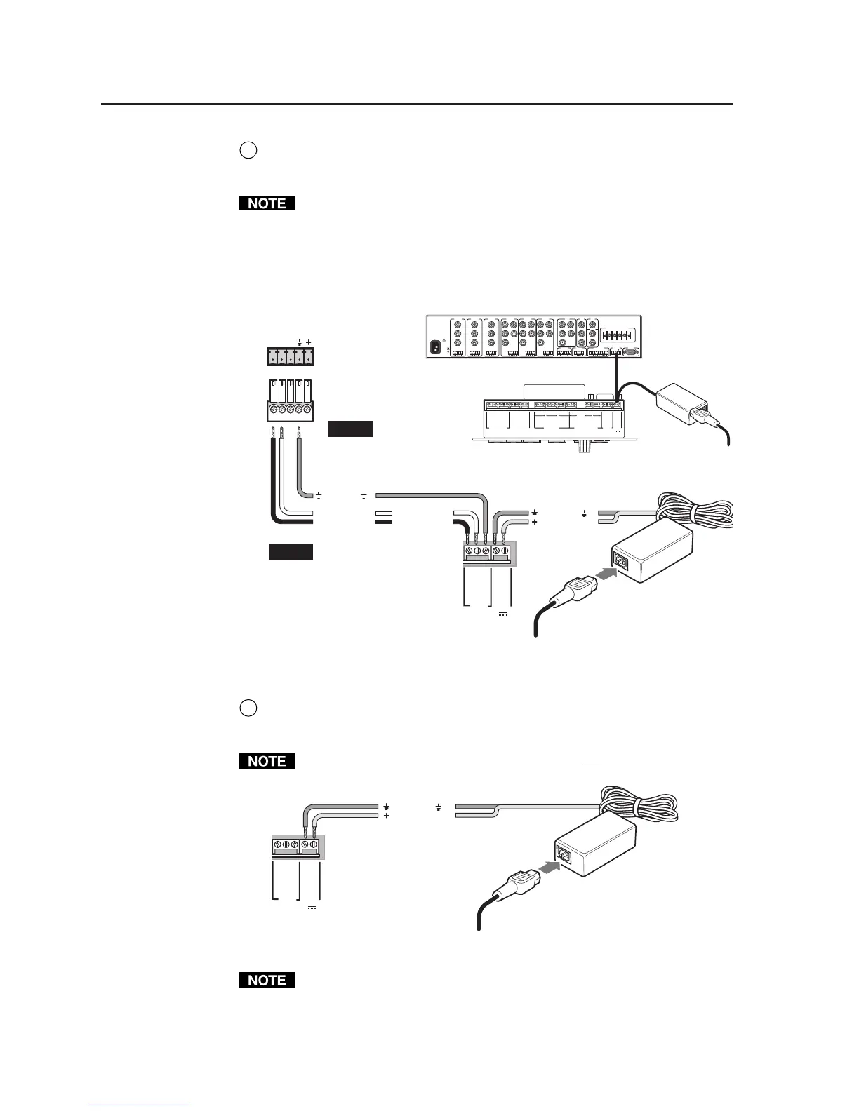
MLS connector — For controlling an optional Extron switcher or other RS-232
controllable device, connect a cable between this 3.5 mm direct insertion
captive screw connector and the RS-232 port of the other device.
The commands issued from this port are standard Extron SIS
™
commands, and
they follow the typical Extron protocol (9600 baud rate, 8 data bits, 1 stop bit,
no parity).
If you connect an optional switcher (such as an Extron MLS Series switcher) to
the MLC, you must connect a ground wire between the switcher and the
MLC, as shown in the following diagrams.
PROJECTOR
RS-232/IR RS-232 12V
CM/ IR SCP
A B C D E
C 1 2
A
RELAYS
IR/SERIAL OUT
MLS PWR
C 3 4
B
C 5 6
C
S G
A
S G
BAB
S G
C
Tx/IR
Rx
GROUND
PWR SNS
GROUND
+12V OUT
Rx
Tx
GROUND
GROUND
+12V IN
+12V OUT
GROUND
CONT MOD
IR IN
SCP COM
MLC/IR
ABC
MLS 506MA Rear Panel
Connecting an MLC 226
to a MediaLink Switcher and
an external power supply
100-240V 0.2A 50/60 Hz
.5A MAX
INPUT 1
VIDEO
Y
C
R-Y
B-Y
YUV
Y
R-Y
B-Y
VIDEO
S-VIDEO
Y
C
INPUT 2
VIDEO
Y
C
R-Y
B-Y
INPUT 3
VIDEO
Y
C
R-Y
B-Y
INPUT 4
RH/
HV
G
V
B
INPUT 5
RH/
HV
G
V
B
INPUT 6
RH/
HV
G
V
B
RGB
RH/
HV
G
V
B
4 ohm
MONO AMPLIFIED OUTPUT
COMM 8 ohm 70V
LR LR LR
LR
AUX/MIXEFFECTS
LR
SEND
LR
RETURN
MLC/IR RS232
CONTACT CLOSURE
ABC
AUDIO OUT
FIXED VARIABLE
LRLR
L LRR LR
MediaLink
Switcher's
rear panel
MLC/IR port
NOTE You must connect
a ground wire
between the MLC
and MLS.
MLC's
MLS and
Power
ports
NOTE If you use cable that
has a drain wire, tie
the drain wire to
ground at both
ends.
MLC 226
Bottom Panel
RS-232 12V
MLS PWR
AB
Rx
Tx
GROUND
GROUND
+12V IN
Ground ( )
Transmit (Tx)
B
Receive (Rx)
A
Transmit (Tx)
Receive (Rx)
B
A
Ground ( )
+12 VDC input
Ground all devices.
External
Power Supply
(12 VDC, 1 A max.
External
Power Supply
6
PWR (power) connector — To provide power to the MLC, connect a cable
between this port and a 12 VDC, 1 amp (maximum) power supply. See the
following diagram.
Power the controller via an external power supply, not from an Extron
switcher. The controller requires a separate 12 VDC power supply.
Connecting an MLC 226
to an external power supply
RS-232 12V
MLS PWR
AB
Rx
Tx
GROUND
GROUND
+12V IN
Ground ( )
+12 VDC input
Ground all devices.
An external
power supply
(12 VDC, 1 A max.)
Check the power supply’s polarity before connecting it to the MLC. See the
following illustration.