2-11MLC 226 Series • Installation: Labeling, Cabling, Mounting
PRELIMINARY
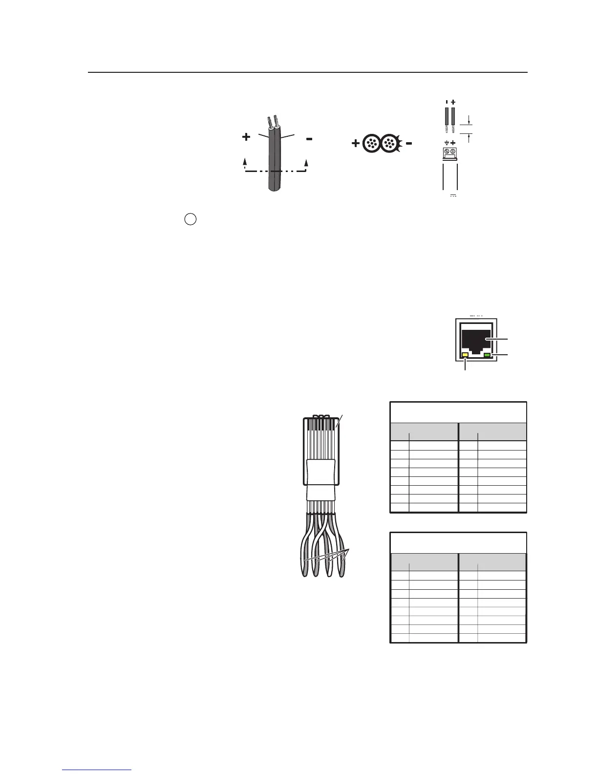
Power Supply
Output Cord
0.2” (5 mm) MAX.
SECTION A–A
Ridges
Smooth
AA
MLC's
Power
Port
12V
PWR
GROUND
+12V IN
Clip Down
1
1&2
3&6
4&5
7&8
2345678
12345678
RJ-45
connector
Twisted
Pairs
Straight-through Cable
(for connection to a switch, hub, or router)
End 1 End 2
Pin Wire Color Pin Wire Color
1 white-orange 1 white-orange
2 orange 2 orange
3 white-green 3 white-green
4 blue4blue
5 white-blue5white-blue
6 green 6 green
7 white-brown7white-brown
8 brown8brown
Crossover Cable
(for direct connection to a PC)
End 1 End 2
Pin Wire Color Pin Wire Color
1 white-orange 1 white-green
2 orange 2 green
3 white-green 3 white-orange
4 blue4blue
5 white-blue5white-blue
6 green 6 orange
7 white-brown7white-brown
8 brown8brown
7
LAN connector and LEDs — An Ethernet connection can be used on an
ongoing basis to connect and to control the MLC 226 (and the devices
connected to it) in an Ethernet network.
Plug a cable into this RJ-45 socket, and connect the other end of the cable to a
network switch, hub, router, or PC connected to an Ethernet LAN or the
Internet.
• For 10Base-T (10 Mbps) networks, use a Cat 3 or better cable.
• For 100 Base-T (max. 155 Mbps) networks, use a Cat 5 cable.
You will also need to configure this port before using it.
Activity LED — This yellow LED blinks to indicate
network activity.
Link LED — This green LED lights to indicate a good
network connection.
• Use a straight-
through cable
for connection
to a switch,
hub, or router.
• Use a
crossover
cable for
connection
directly to a
PC. Wire the
connector as
shown in the
tables at right.
Configure the
settings for this
port via either SIS commands or the
Windows-based configuration
program. See the programming
sections of this manual (chapters four
and five) for details.
LAN port defaults:
• MLC’s IP address: 192.168.254.254
• gateway’s IP address: 0.0.0.0
• subnet mask: 255.255.0.0
• DHCP: off
RJ-45
Port
Link
LED
Activity
LED