Installation and Operation
VTG 400/400D • Installation and Operation2-4
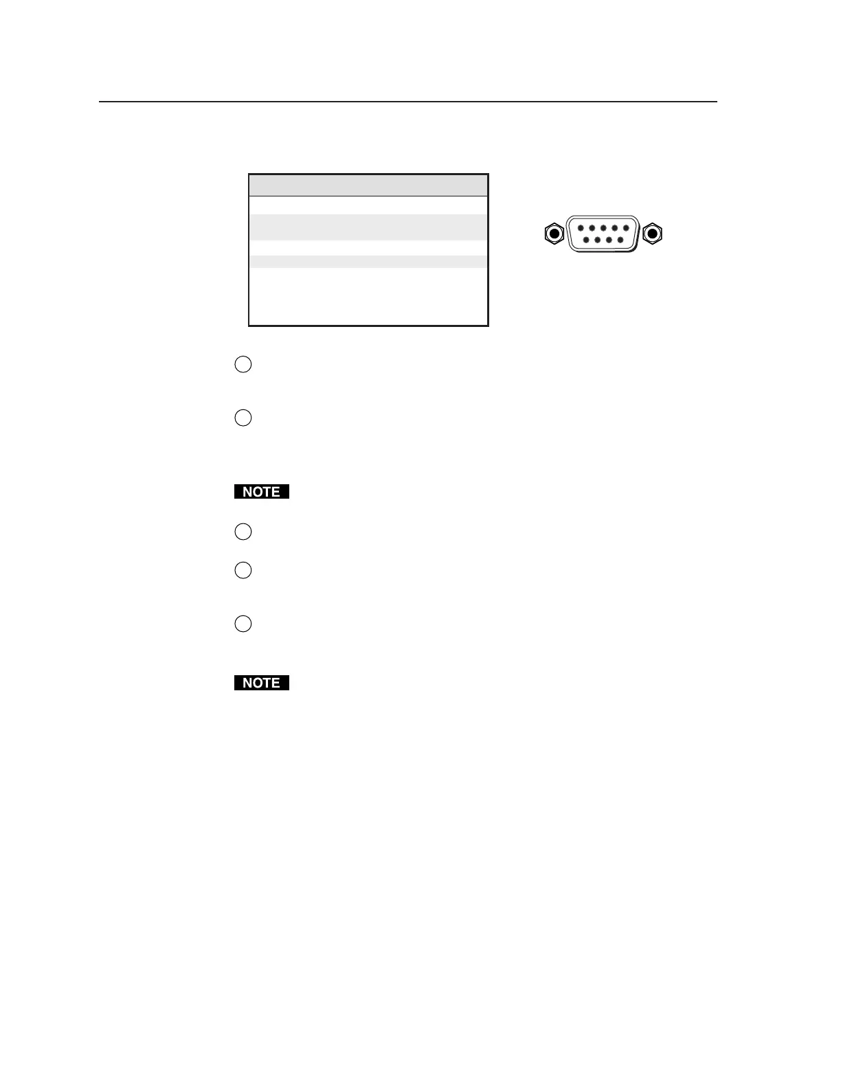
The rear panel RS-232, 9-pin connector has the following pin assignments:
Pin RS-232 function Description
1 – No connection
2 Tx Transmit data
3 Rx Receive data
4 – No connection
5 Gnd Signal ground
6 – No connection
7 – No connection
8 – No connection
9 – No connection
DB9 Pin Locations
Female
51
96
8
SDI/HDSDI serial digital interface output connector (VTG 400D only) —
Connect an output device to the SDI/HDSDI component output female
BNC.
9
Trigger output connector — Connect an oscilloscope to this female BNC
connector when using an oscilloscope to align its display to a specific point
in the video waveform.
The oscilloscope’s external trigger needs to be configured to accept a TTL
level (0 to 5 V) signal.
10
RCA jack (Audio output 1) — Unbalanced mono audio is output from this
female jack. See the note below.
11
3.5 mm mini stereo phone jack (Audio output 2) — Unbalanced mono
audio on both left and right channels is output from this female mini phone
jack. See the note below.
12
XLR audio output connector (Audio output 3) — Balanced mono audio is
output from this 3-pin male connector.
See Connecting Audio Outputs later in this chapter for audio wiring
instructions.
Tel. 07131 911201
Fax 07131 911203