Installation and Operation, cont’d
VTG 400/400D • Installation and Operation2-8
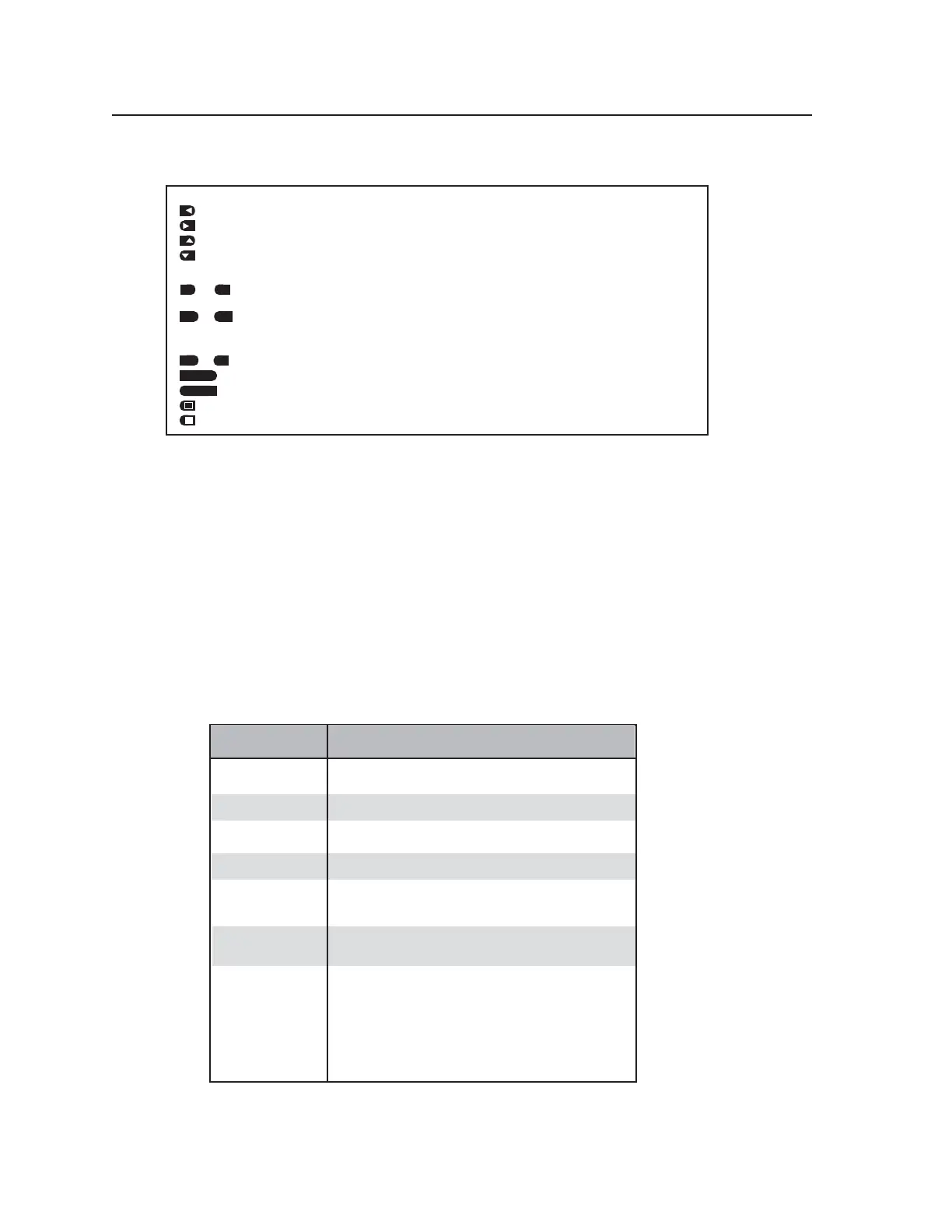
Function Option Icons
Cursor movement and option selection
— Press the button next to this icon to move the cursor left or select an option at the left of the LCD.
— Press the button next to this icon to move the cursor right or select an option at the right of the LCD.
— Press the button next to this icon to increment or scroll up to the next selection.
— Press the button next to this icon to decrement or scroll down to the previous selection.
State indication and option selection
or — This icon indicates the function is on/active. Press the button next to this icon to toggle the
“on” state to “off”.
or — This icon indicates the function is off/not selected. Press the button next to this
icon to toggle
the “off” state to “on”.
Option selection
or — Press the button next to this icon to select “yes” or “no”.
— Press the button next to this icon to save the current settings.
— Press the button next to this icon to cancel (not save) the current settings.
— Press the button next to this icon to invert the test pattern.
— Press the button next to this icon to return the test pattern from the inverted state to the original state.
CANCEL
SAVE
SAVE
YES
NO
ON
OFF
ON
OFF
Audio Testing Features
The VTG 400/400D can selectively output seven different audio signal formats. The audio level
can also be selected from a range of levels available for each audio format.
Depending on the audio signal format, the audio frequency may be selected from a range of
values.
See the Top Panel Features section earlier in this chapter for button descriptions.
Selecting audio signals
The following table summarizes the seven audio signal formats available through the VTG.
Pressing the Signal Type button repeatedly scrolls through the signals and displays the signal type
on the LCD.
AUDIO
SIGNAL FORMAT
DESCRIPTION
Pink Noise
White Noise
Sine Wave
Random noise that has constant energy per octave.
Used in loudspeaker testing and calibration.
Random noise that has an equal energy distribution
across all frequencies between 20 Hz and 20 kHz.
Used in detecting distortion. The frequency can be set
from 20 Hz to 20 kHz (in 1/12 octave steps).
Square W
ave
Frequency Sweep
Polarity test
Sine Burst
Square wave signal with 50% duty cycle and no DC offset.
The frequency can be set from 20 Hz to 5 kHz.
Varies the frequency of a sine wave signal continuously
over the specified frequencies. Used to detect driver
defects and mechanical sources of distortion.
Generates a sine wave of a specified frequency that is gated
on and off for fixed intervals. Used in testing the transient
response of audio systems.
• The burst interval is defined by the total number of cycles
(on and off) in each repeating period.
• The burst on duration is defined by the number of cycles
in the interval where the sine wave is
turned on.
See the burst signal example below.
Pulsed waveform (1 Hz pulse, positive-going, pulse width =
1ms, duty cycle = 0.1%) used in verifying the polarity of
audio wiring.
Tel. 07131 911201
Fax 07131 911203