Appendix, cont’d
VTG 400/400D • AppendixA-12
below 100% white by eight steps to 94.5% and upward above reference white to
105.5% in eight steps. Each step represents a 0.685% change. Adjusting contrast
(gain) so that each step above 100% is just visible ensures that peak video
changes and details near white are preserved.
Conversely, the shallow ramps near black at the bottom of the pattern show
performance near black. The shallow ramp extends downward below black (0%)
by eight steps to -5.5% and upward to +5.5% in eight steps. Each step represents
a 0.685% change. Adjusting brightness (black level) so that each of the steps
below 0% is just visible ensures that peak video changes and details in the
shadows are preserved.
The center of the pattern includes a regular 15 step split grayscale for
convenience and serves the same function as the split grayscale pattern
described earlier.
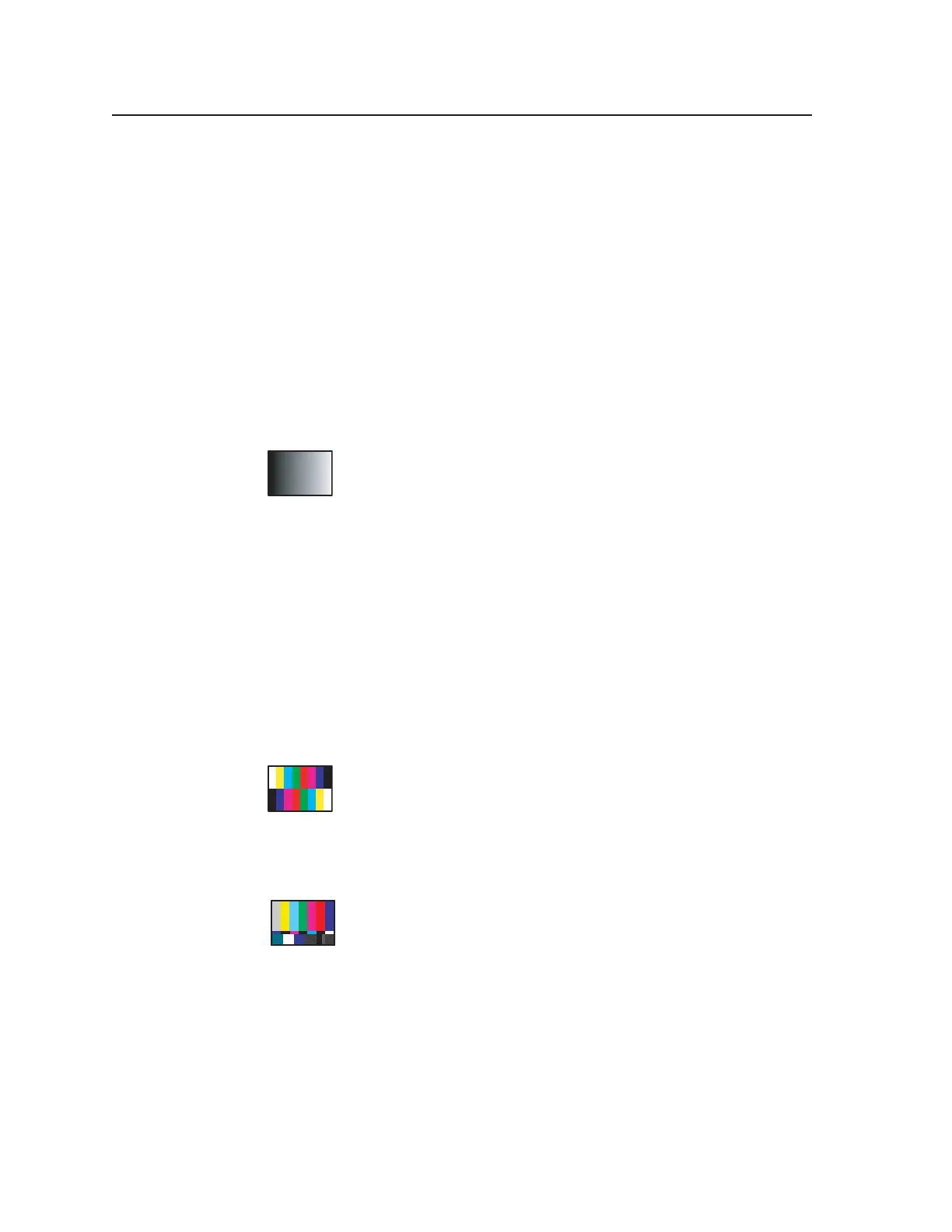
12. Ramp
The ramp pattern is commonly used to evaluate display
performance in the area of pixel depth capability. Since the creation
of image test patterns using digital technology, the industry
acknowledges that a minimum pixel depth of 8 bits per pixel (256
levels) is the minimum pixel depth requirement for perception of continuous
tones in colors and grayscale for each of the primary colors (i.e. red, green, and
blue). The VTG utilizes 10-bit pixel depth for creation of all its test patterns. This
provides four times more resolution for shades of colors or levels of gray than 8-
bit systems.
The gradual change in light output across the ramp should appear smooth
without any noise, banding, or other inconsistencies. Displays and processors
having less than 8 bits per pixel per color may exhibit periodic vertical bands
along the ramp pattern, commonly called contouring. The ramp pattern, due to its
gradual level change, can be used to highlight specific points where image
processing noise may become visible.
13. Color Bars (8-color split)
For graphics line rates, this color bar pattern is helpful in verifying
correct cable connections for red, green, and blue signals. It may be
used to facilitate setting of video levels and check for low frequency
crosstalk between the color channels. General uses include
verification of relative color timing, saturation, and level adjustment.
SMPTE Color Bars (with PLUGE pattern)
Designed for NTSC video systems, this pattern was standardized
by the Society of Motion Picture and Television Engineers for proper
alignment of the NTSC color transmission system. This color bar
pattern is used to evaluate NTSC color decoding systems and assist
in proper setup of the color and tint (hue) controls in an NTSC television monitor
or receiver. The PLUGE pattern contained in the lower right section of the
pattern is used to set proper black level as described for the dedicated PLUGE
pattern available from the VTG 400.
The small complimentary color rectangles at the bottom of the larger color bars
are used to facilitate color and tint calibration. In order to properly calibrate the
color and tint controls, some method of suppressing the red and green channels
is necessary so that only the blue content of the color bar signal is in use. This
may be done by viewing the test pattern through a blue filter, by switching to the
“blue only” mode available on some monitors, or by removing the red and green
Tel. 07131 911201
Fax 07131 911203