A-19VTG 400/400D • Appendix
26. Contrast Transfer Function (CTF)
The Contrast Transfer Function (patent pending), or CTF, provides
an indication of overall system high frequency response including
the display’s optical path. While most high frequency test patterns
provide electrical bandwidth performance information when used
with appropriate test instruments, evaluation of overall system response,
including the optical pathway, is virtually nonexistent. Good high frequency
performance translates to the perception of contrast and detail in the image. As
high frequency performance degrades, contrast ratio between high and low
image transitions approach middle gray and appear muddy or non-distinct.
Should high frequency transitions become fully attenuated, the contrast falls to
zero.
The CTF pattern contains bursts of high frequency alternating pixels and bursts
of low frequency lines. Both appear as vertical bands on the screen. In the
default mode, the alternating pixel bursts flash On and Off at a rate of 0.5 second,
or 2 Hz. Pushing the soft key on the VTG’s display screen defeats the flashing
effect, if desired.
The low frequency line bursts will pass through a display system with less
relative attenuation than the high frequency bursts. Since the high frequency
bursts will appear to approach middle gray and lose detail when system
response is degraded, the user may adjust the level of the low frequency bursts
up or down via the soft keys on the VTG control display to match the perceived
brightness of the high frequency bursts. When the point is reached where the
perceived brightness of all the bursts is equal, the VTG provides a percentage
number on its display. This percentage number is the approximate percentage of
contrast performance in the system, including electrical and optical pathways. It
may be used as a relative index of performance for the system’s bandwidth.
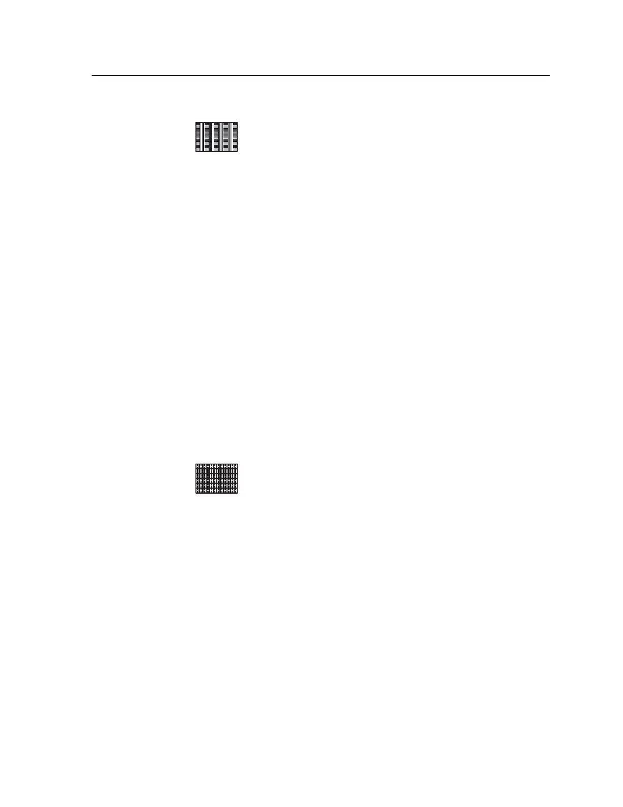
27. H Pattern
The H pattern represents simple text that can be used to evaluate
image sharpness or overall response quality using symbology that
anyone can understand. The invert soft key on the VTG 400
reverses the text from white text on a black background to black text
on a white background. Use the H pattern for high frequency response
evaluation where text legibility is the most critical application. This pattern may
also be used to evaluate transient response, focus, lens distortions, video
clamping stability, and image sharpness.
Tel. 07131 911201
Fax 07131 911203