2-9VTG 400/400D • Installation and Operation
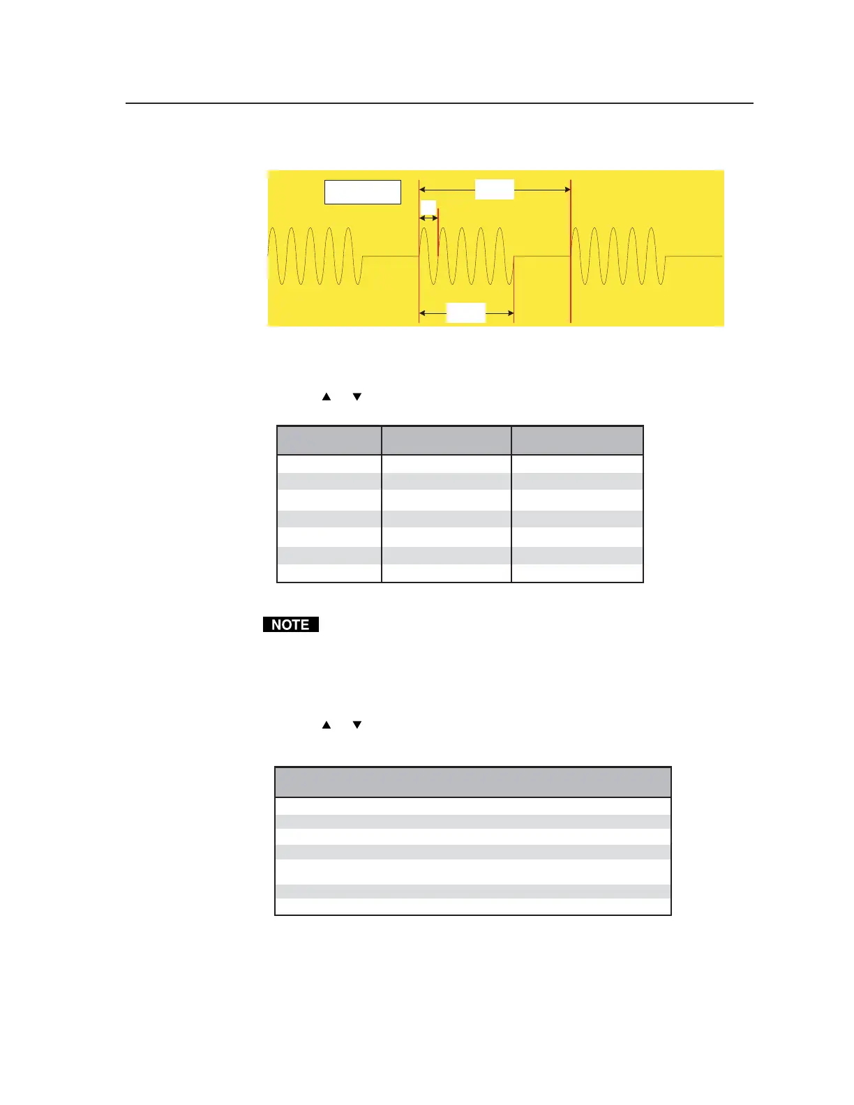
An example of the sine burst signal is shown in the following illustration:
Interval
= 8 Cycles
Burst On
= 5 Cycles
Burst Frequency
= 1 / Cycle
1
Cycle
Setting the audio level
The audio level for each audio signal type is selected from a range of values
using the
or Level buttons. The following table lists the range of values.
Audio Audio Level Range Audio Level Range
Signal Format (in dBu increments) (in dBV increments)
Pink Noise -4 dBu to -72 dBu -6 dBV to -74 dBV
White Noise +6 dBu to -72 dBu +4 dBV to -74 dBV
Sine Wave +6 dBu to -72 dBu +4 dBV to -74 dBV
Square Wave +6 dBu to -72 dBu +4 dBV to -74 dBV
Frequency Sweep +6 dBu to -72 dBu +4 dBV to -74 dBV
Polarity Test -14 dBu to -72 dBu -16 dBV to -74 dBV
Sine Burst +6 dBu to -72 dBu +4 dBV to -74 dBV
Displayed levels are for high impedance loads. For 600 ohm loads, there is
a -0.7 dB (unbalanced) / -1.3 dB (balanced) difference between the displayed
and actual levels.
Setting the audio frequency
The audio frequency for each audio signal type is selected from a range of values
using the
or Audio Frequency buttons and observing the LCD. The
following tables list the available frequencies.
Audio
Signal Format Audio Frequencies
Pink Noise N/A
White Noise N/A
Sine Wave 20 Hz through 20 kHz (see the following Audio Range chart)
Square Wave 20 Hz through 5 kHz (see the following Audio Range chart)
Frequency Sweep Sweep speed (in seconds): 120, 90, 60, 30, 20, 10, 9.0, 8.0, 7.0, 6.0,
5.0, 4.0, 3.0, 2.0, 1.0
Polarity Test 1 Hz
Sine Burst 20 Hz through 20 kHz (see the following Audio Range chart)
Tel. 07131 911201
Fax 07131 911203