A-13VTG 400/400D • Appendix
cables from the display input if the decoding process is being handled in an
external video processor.
The small blue rectangle under the white bar and the small white rectangle
under the blue bar are used to indicate proper threshold of the color control level.
While viewing the blue bars, adjust the color level control until the perceived
brightness of the small rectangles merges with the larger bars to yield one
consistent intensity.
Now, adjust the tint control by viewing the small rectangles under the cyan and
magenta bars. Adjust the tint control until those bars merge into one long bar of
consistent intensity. There may be interaction between color and tint, so,
alternately adjust each control using this procedure until the blue bars across the
screen are all of consistent intensity. This ensures proper adjustment of the color
decoder. The inability to achieve an even intensity indicates the presence of color
decoder errors.
Note that composite NTSC video utilizes a 7.5 IRE setup pedestal for the black
level. The S-video format is likely to include the setup pedestal depending on the
source system and the methodology for signal creation. The VTG 400 includes
the setup on the S-video luminance signal output and on the component Y
channel output. Digitally-produced component NTSC or decoded NTSC (into
the RGB domain) does not utilize the setup pedestal. This difference can account
for a significant shift of black level when calibrating displays for multiple signal
sources and formats.
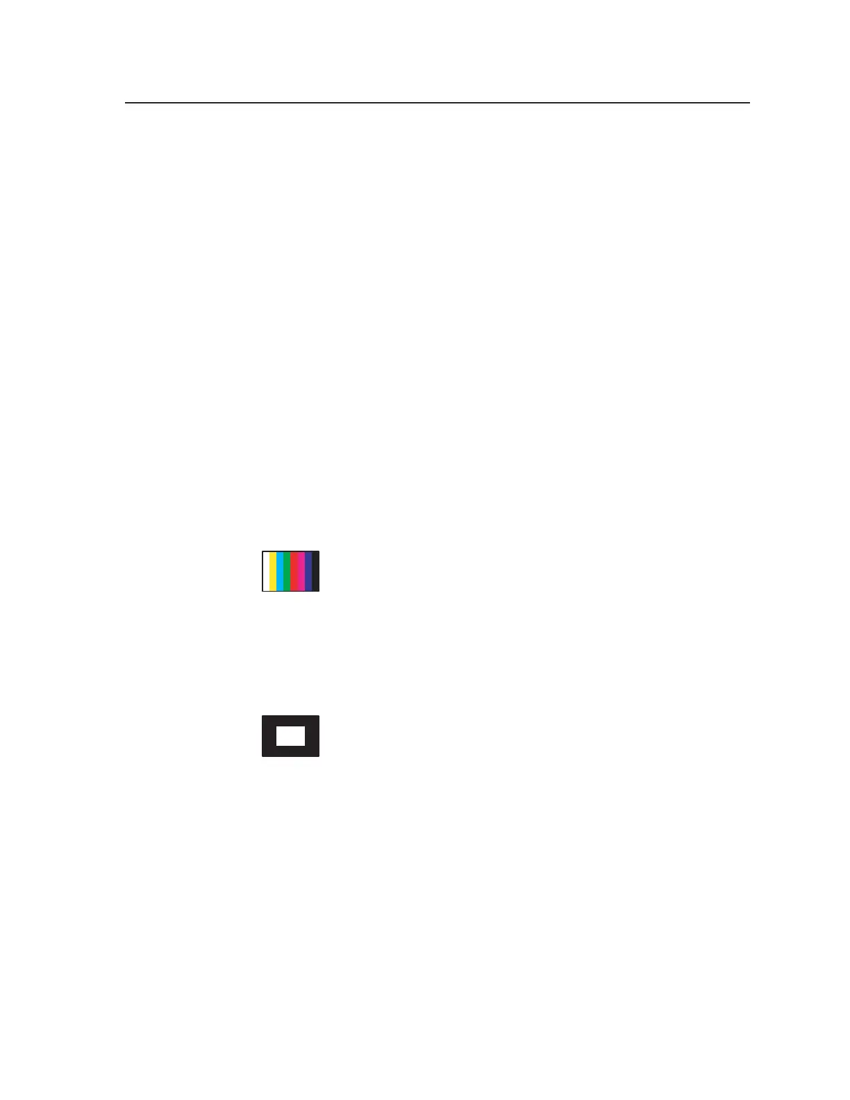
EBU Color Bars (8-color full bars)
The EBU color bars are used by European television personnel
transmitting PAL (Phase Alternating Line) television signals. Its
function is identical to the NTSC color bars except that it is made up
of eight single bars with no provision for color saturation setup or
PLUGE. The PAL system, by design, does not require a tint control on the
receiver’s decoder. Therefore, tint calibration is not required. Note that the PAL
transmission standard does not utilize a setup pedestal. Therefore, black level
reference in the signal is consistent regardless of format.
14. Window 80%
Window patterns provide a low duty cycle white, or near white,
reference at screen center for performing grayscale setup without
driving the display into a nonlinear operating condition. In
particular, driving CRT-based projectors with high duty cycle
signals causes an overdrive condition. Therefore, the 80% gray level of this
pattern is a good choice for setup of highlight values when performing grayscale
setup of a display where light output efficiency may not rival that of a direct-
view display.
Using the 80% window as the highlight value for performing color of white
measurement with a colorimeter typically does not overdrive the projection
system. When using a colorimeter, or other suitable light measurement device,
the gain or highlight controls are adjusted to provide the correct color of white
during grayscale calibration. The 80% window pattern is located “next door” to
the 20% level window pattern to facilitate quick switching between high and low
duty cycle window patterns in order to streamline the grayscale calibration
procedure.
Tel. 07131 911201
Fax 07131 911203