Installation and Operation, cont’d
VTG 400/400D • Installation and Operation2-14
Video Setup menu
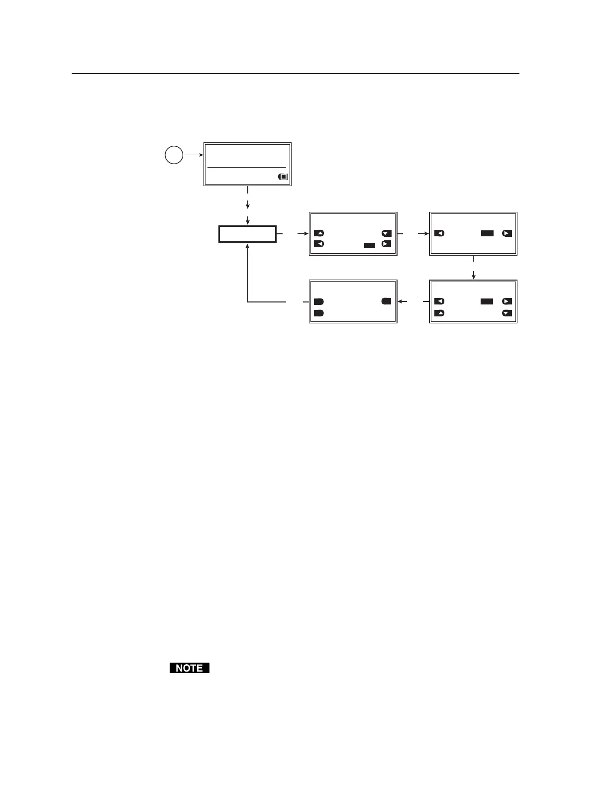
The following flowchart describes the Video Setup menu.
VIDEO
SETUP
MENU
MENU
NEXT
NEXT
Power
on
RES: VGA 640x480
FRQ: 31.50kHz 60.00Hz
PAT: Fine Crosshatch
SIG: Pink noise FRQ: N/A
LEV: -10 dBu 245mV
VIDEO SETUP: <1 of 4>
RGB Sync Format
RGBHV
Raster Border:
ON
VIDEO SETUP: <2 of 4>
On-Screen Display:
ON
NEXT
NEXT
NEXT
VIDEO SETUP: <3 of 4>
Auto Sequence Mode:
ON
Auto Sequence Interval:
15 seconds
OFF
VIDEO SETUP: <4 of 4>
RGB Color Channel Enable:
RED GREEN
BLUE
OFF
OFF
ON
ON
ON
Video Setup menu
Video Setup submenu (1 of 4)
The RGB sync format and a raster border are specified from this submenu.
RGB sync format
Specify the RGB sync format.
• RGBHV (default)
• RsGsBs
• RGsB
• RGBS
Raster border
A one-pixel-wide white border around the edge of the active area can be enabled
(on) or disabled (off).
• ON
• OFF (default)
Video Setup submenu (2 of 4)
The test pattern’s on-screen display can be enabled (on) or disabled (off) from
this submenu.
On-Screen Display
• ON
• OFF (default)
When set ON and a new output rate is activated, the VTG displays the rate
type, rate frequency, and resolution for 4 seconds. The text is identical to
what is displayed on the VTG’s LCD display and appears as white text in a
black box centered on the test pattern. See the following example
illustration.
Tel. 07131 911201
Fax 07131 911203