Appendix, cont’d
VTG 400/400D • AppendixA-16
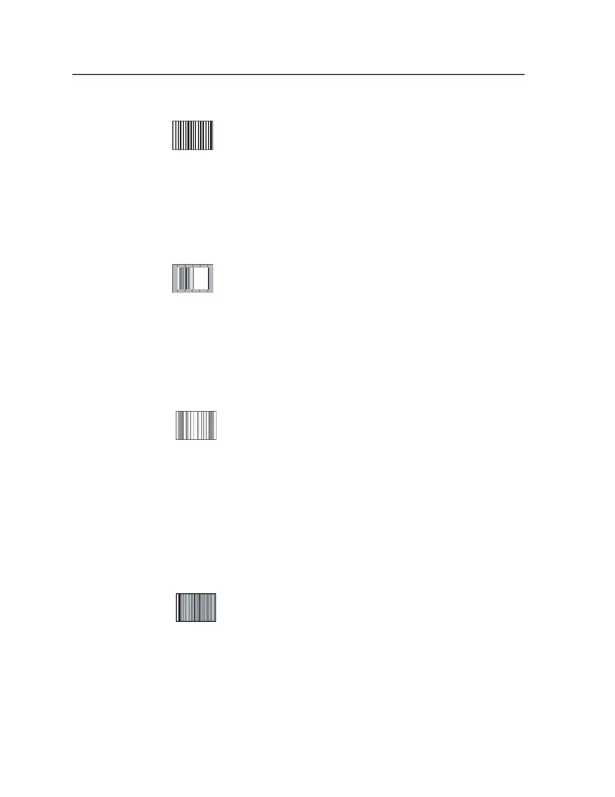
22. Alternating Pixels (1 on, 1 off)
For computer graphics displays, alternating pixels represent the
highest frequency operation at a given line rate, or resolution. These
one-On, one-Off transitions tax the speed of a graphics system and
the display’s performance as well. Use this pattern to assess the
high frequency performance of the display or a graphics system in total. It may
also be used to align or evaluate pixel timing and phase on fixed pixel displays.
As a source for EMI testing, the alternating pixel pattern represents a worst case
scenario for products that may radiate energy in relation to FCC regulations.
Typically, an oscilloscope is used to measure the true performance of the display
system using this pattern.
Frequency Sweep
Within the NTSC or PAL environment, the frequency sweep pattern
provides a sine wave sweep from near DC to the specified system
bandwidth for the affected broadcast standard. This pattern is used
to evaluate system bandwidth performance and is also used to
evaluate color decoder performance in the region of the chroma subcarrier
frequency.
The sweep limit for NTSC is 4.2 MHz and the sweep limit for PAL is
5 MHz. While some visual information can be derived from viewing this pattern
on a display, bandwidth evaluation is most accurately accomplished using an
oscilloscope or waveform monitor.
23. Graphics Multiburst
The graphics multiburst provides groups of digital bursts
consisting of 1/1 (meaning one-On, one-Off) alternating pixels at
screen center flanked by 2/2 alternations, then 4/4 alternations,
8/8 alternations, and a white reference. Perception of grayscale
should remain consistent throughout; otherwise, frequency response differences
will cause color shifts, particularly in the 1/1 burst as compared to the other
bursts.
Utilizing an oscilloscope, this pattern may be used to evaluate high frequency
versus low frequency performance of a graphics system. The border area
between bursts is 50% gray. Anomalies of high frequency performance resulting
in severe attenuation of the center burst of 1/1 pixels blend into the middle gray
border. In addition, color shifts are most easily identified against the low
frequency nature of the middle gray level.
Multiburst
The television multiburst is intended to provide rapid evaluation of
system bandwidth over the television channel using a waveform
monitor or oscilloscope. A full bandwidth system reproduces the
multiburst with all bursts having equal amplitude from low
frequency to high frequency. Visually, the pattern may be used to see the relative
quality or effect on bandwidth of the color decoder system and luminance
channel.
Each version of the multiburst includes one burst at the system subcarrier
frequency so that luminance channel attenuation due to the quality of the color
decoding system may be observed. Each burst is symmetrical about a 50%
(middle gray) pedestal. Following are the basic specifications for the two
multiburst formats in the VTG 400:
Tel. 07131 911201
Fax 07131 911203