2-3VTG 400/400D • Installation and Operation
Rear Panel Connectors and Cabling
RS-232
50-60Hz
COMPOSITE
RG BH/HVV
S-VIDEO R-Y Y B-Y RGB
TRIGGER
1
SDI/HDSDI
100-240V 0.3A
LISTED
1T23
I.T.E.
AUDIO
2
3
4
1 2 3 6 9 10 11 12
8
7
5
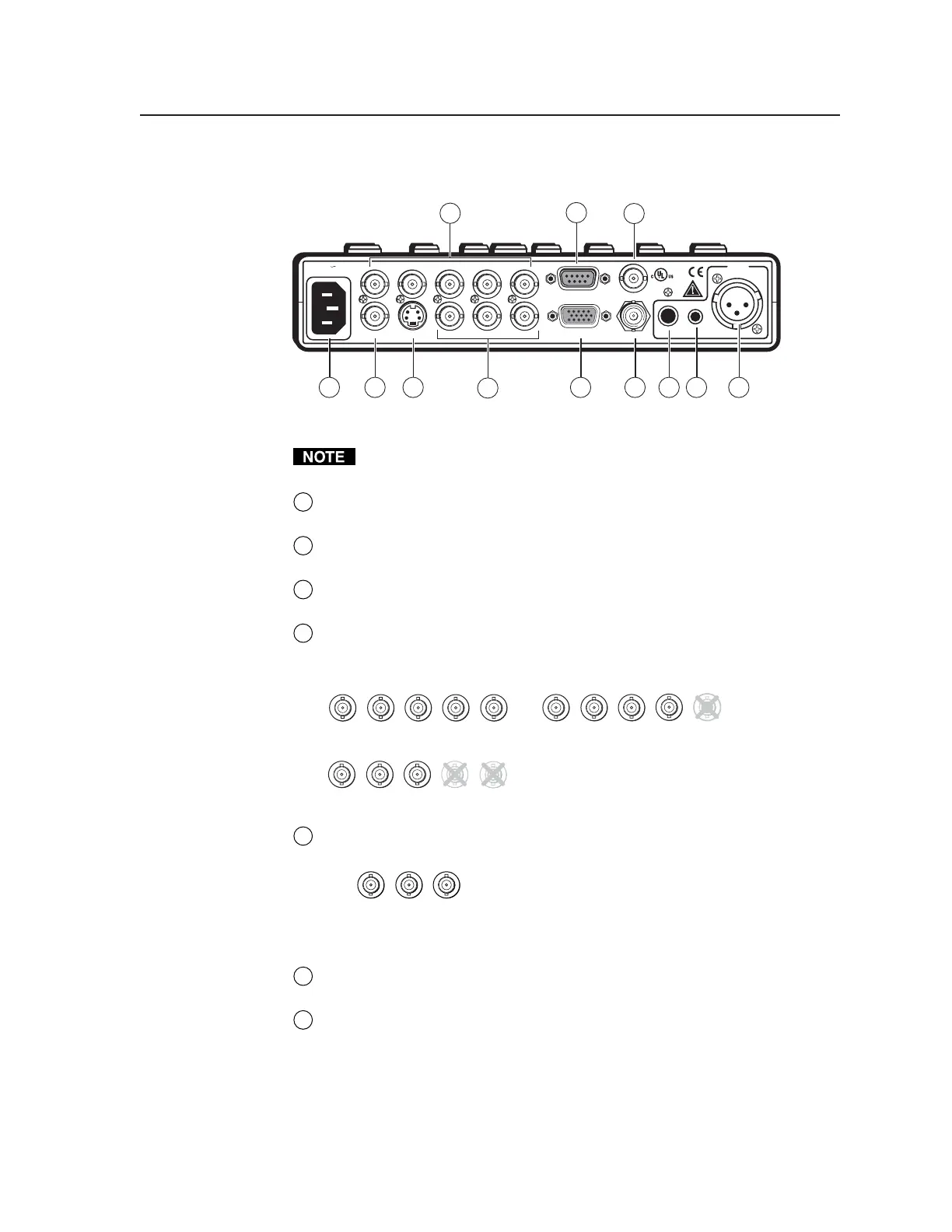
VTG 400 and VTG 400D rear panel connectors
RGB video, component video, composite video, S-video, and SDI/HDSDI
(VTG 400D only) video are output simultaneously.
1
AC power connector — Plug a standard IEC power cord into the connector
to connect the VTG to a 100 to 240 VAC, 50 Hz or 60 Hz power source.
2
Composite video output connector — Composite video is output through
this BNC connector.
3
S-video output connector — S-video is output through this 4-pin mini DIN
connector.
4
RGB computer video output connectors — Connect a display device to the
five female BNC connectors for RGBHV, RGBS, RGsB, or RsGsBs video
output, as follows:
RGBHV output
RGBS output
R
G
B
V
H
/HV
R
G
B
V
H
/HV
R
G
B
V
H
/HV
RGsB, RsGsBs output
5
R-Y, Y, B-Y component video output connectors — Connect a display
device to the three female BNC connectors for component video output:
Component video output
(R-Y, Y, B-Y)
R-Y
Y
B-Y
6
15-pin RGB output connector — RGBHV, RGBS, RGsB, and RsGsBs are
output through this 15-pin HD connector.
7
RS-232 port — This 9-pin female D connector provides for two-way RS-232
communication. See chapter three, “Serial Communication”, for
information on how to install and use the control software and SIS
commands.
The default protocol is 9600 baud, 1 stop bit, no parity, and no flow control.
Tel. 07131 911201
Fax 07131 911203