A-11VTG 400/400D • Appendix
side are visible. The dimmer of the two is +2%, and the brighter is +4% above
black. If either or both of the brighter bars are not visible, the black level is set too
low. When the test pattern background is illuminated such that the “blacker-
than-black” bar is discernible against the black surround, the black level is set
too high.
Contrast Gain
The group of four illuminated boxes in the center region of the test pattern are
used solely for contrast control adjustment. The intensities of the boxes are 25%,
50%, 75%, and 100% from bottom to top. Included within the 100% white box is a
95% box. The contrast control (or system gain) should be adjusted using this
pattern until no further increase in contrast produces additional light output
from the 100% box. With traditional CRT displays, the white box would “bloom”
out of focus, lose all line definition, and tend to distort. It typically would also
shift toward yellow (indicating a lack of blue light output) when the threshold of
nonlinearity is achieved. The correct setting is just prior to any or all of these
described conditions.
For fixed pixel displays, such as LCD, DLP, or LCoS, where the imaging element
is merely controlling the amount of light transmitted or reflected, the display
system attains maximum light output, and any further adjustment results in no
visible change of brightness. Adjusting past the threshold of maximum light
output results in the clipping of highlight details close to white by “pushing”
them into the full white output region of the display.
This point of maximum light output is difficult to visually gauge. Use the 95%
box within the 100% box as an indicator for the correct gain setting. Just when
the 95% box begins to climb in brightness and approaches the 100% setting, the
point of maximum is reached. If the gain setting is too high, the 95% box merges
into the full white presentation of the 100% box. Furthermore, the luminance of
the three lower boxes rises to a point where they become white and merge with
the 100% box. This condition represents an adverse setting of the system gain.
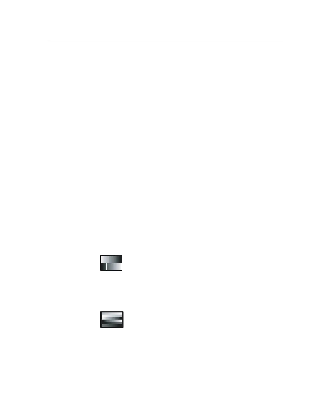
10. 32-Level Split Grayscale
This pattern is used to assess grayscale tracking, or consistent color
of gray, from black to white. The ability of a display to render an
accurate image rests with its ability to faithfully reproduce a linear
grayscale. There should be no perceived color shift across the
presentation of gray levels. Any color shift seen within this pattern manifests as
a change in color hue or rendition within all imagery as intensities change from
dark to light.
11. Extreme Grayscale
This pattern reveals the display’s ability to produce subtle
grayscale near the extreme white and black portion of the display’s
dynamic range. As the display system approaches full white or
black, slight changes in luminance output convey shadow and
detail near these extremes.
Displays must be capable of fully linear reproduction in order to exhibit good
control near the extreme ends of the image range. Incorrectly adjusted contrast
(gain) and brightness (black level) controls cause loss of important details near
white and black. The extreme grayscale pattern allows easy evaluation of
display setup for this important parameter.
The shallow ramps near white at the top of the pattern show performance near
white. The center level is 100% white. The shallow ramp extends downward
Tel. 07131 911201
Fax 07131 911203