Appendix, cont’d
VTG 400/400D • AppendixA-8
Test Patterns in Detail
The following test patterns descriptions are helpful in determining how and
when the VTG’s array of test patterns can be used. The numbers correspond to
the test patterns in the previously described Test Patterns Chart.
1. Circles
White circles on a black background are useful for checking overall
image geometry and linearity. The invert feature converts the
pattern to predominantly white, which may also be used to evaluate
white field uniformity as well as geometry across the screen.
Projectors having low quality optics may show chromatic aberrations of the test
pattern, especially in the corners. Chromatic aberrations manifest when the
projection lens functions as a prism and separates light into its component
colors. Utilizing this pattern, chromatic aberration is seen as a separation of red,
green, and blue typically toward the corners of the image area.
When used in the 16:9 format, the pattern shows the small circles in the extreme
corners of the test pattern. The 4:3 format version, if displayed on a 16:9 display
in the widescreen mode, shows the circles as being more egg-shaped. The
centered vertical line and horizontal line form a crosshair target indicating the
exact center of the image.
2. Safe Area (5%/10%)
Television receivers (typically CRT-based types) commonly extend
the image raster beyond the edges of the display, which is a practice
called overscanning. Overscanning hides image nonlinearities and
raster scan artifacts as well as production test patterns typically
hidden within the last few lines of the vertical blanking interval.
The safe area pattern thus becomes a guide for the technicians in the television
production environment to show the likely amount of cropped display area on a
typical consumer television receiver. The outer rectangle indicates a 5% crop
area, which is the minimum amount of overscan for picture information. The
inner rectangle represents a 10% crop area and is referred to as the “safe title
area”.
By maintaining all key action within the rectangle representing the 5% crop area,
the producer can guarantee that the viewer will be able to see all of the intended
information. By maintaining all titles inside the area bounded by the 10% safe
area marker, all text and titling will be seen by the viewer. The centered vertical
line and horizontal line form a crosshair target indicating the exact center of the
image.
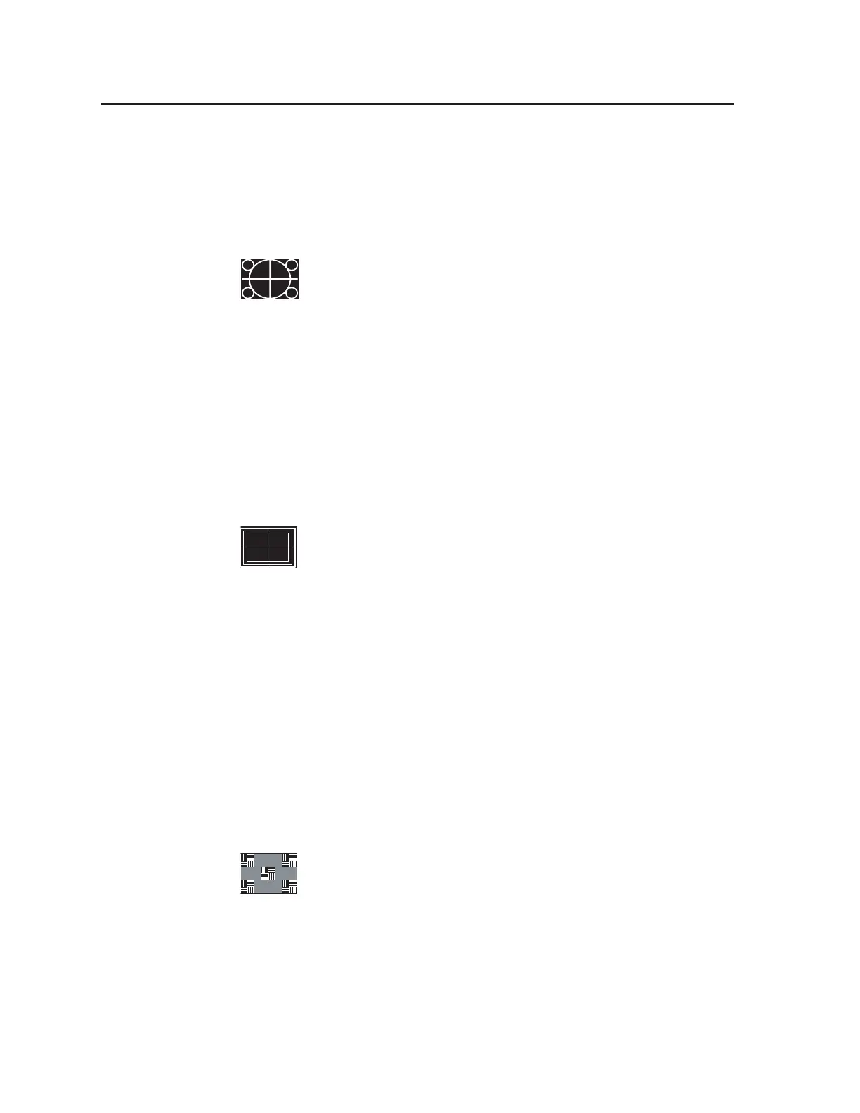
3. Focus
The focus test pattern tests the depth of field of the projector lens.
Low quality lenses do not display the corners of the test pattern with
equal sharpness to the center; or, the corners do not appear the same
as the center. The focus patches represent a combination of high
frequency detail (vertical lines) as compared to low frequency information
(horizontal lines). These patches should be equal in brightness and color hue
when a video system has an overall flat frequency response.
When high frequency response suffers significantly, the patches of vertical
alternating pixels blend toward a 50% gray level. Since the background is 50%
gray, the patches tend to disappear within the background. Comparing the
patches to the background assists in making this evaluation.
Tel. 07131 911201
Fax 07131 911203