Digital Brushless AC Servo Drive system - Ref. 1809 BCSD-61/116
2. Brake interlock output.
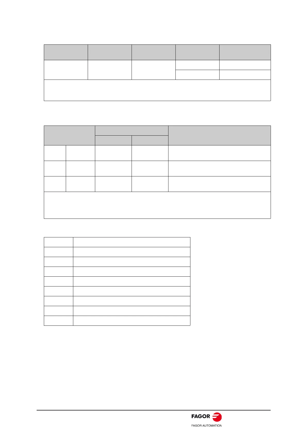
3. Allocating Brake Interlock Output (/BK).
Brake interlock output (/BK) is not used with the factory setting. The output signal must be allocated.
Parameter Pn511 description as following:
Type Signal Name
Connector Pin
Number
Setting Meaning
Output /BK Must be allocated
ON (Low level) Releases the brake.
OFF (High level) Applies the brake.
This output signal controls the brake and is used only for a servomotor with a brake. This output signal is not
used with the factory setting.The output signal must be allocated by Pn511. It does not need to be connected
for servomotor without a brake.
Parameter
Connector Pin Number
Meaning
+ Terminal - Terminal
Pn511 H.
4 CN1-11 CN1-12
The /BK signal is output from output terminal CN1-
11,12.
Pn511 H.
4 CN1-5 CN1-6
The /BK signal is output from output terminal CN1-
5,6.
Pn511 H.
4 CN1-9 CN1-10
The /BK signal is output from output terminal CN1-
9,10.
- Important:
When set to the factory setting, the brake signal is invalid.
For the allocation of servodrive output signals other than /BK signal, refer to 3.2.2 I/O Signal Names and
Functions.
0 /COIN (/V-CMP) output
1 /TGON rotation detecting output
2 /S-RDY servo drive get ready output
3 /CLT torque limit output
4 /BK brake interlock output
5 /PGC encoder C pulse output
6 OT overtravel signal output
7 /RD servo enabled motor excitation output
8 /HOME home completion output
 Loading...
