Operation
4812164601_C.pdf2023-01-05
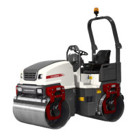
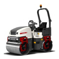
Edge cutting (Optional)
19
20
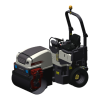
Fig. Instrument panel
19. Edge cutter / compactor,
Right / Left
20. Edge cutter / compactor, Up / Down
The machine must be running to activate the edge
cutter/compactor.
Selection of edge cutter / compactor for right or left is
done with the button (19).
With the machine in Working mode/Edge cutter (20)
(middle LEDs lit) the edge cutter/compactor is
controlled up and down with the help of button (3) and
button (2) on the control lever.
The edge cutter/compactor can always be moved
upwards, irrespective of the position selected on the
button Working mode (20). Also in Transport mode
(0 LEDs lit) the edge cutter/compactor can be moved
upwards, with button (3).
A bypass valve prevents the hydraulic system
being overloaded.
The operator should use the ordinary sprinkler system
to avoid asphalt sticking to the edge cutter/compactor,
and open the ball valve (5) by the separate sprinkler
nozzle on the edge cutter/compactor.
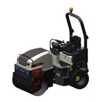
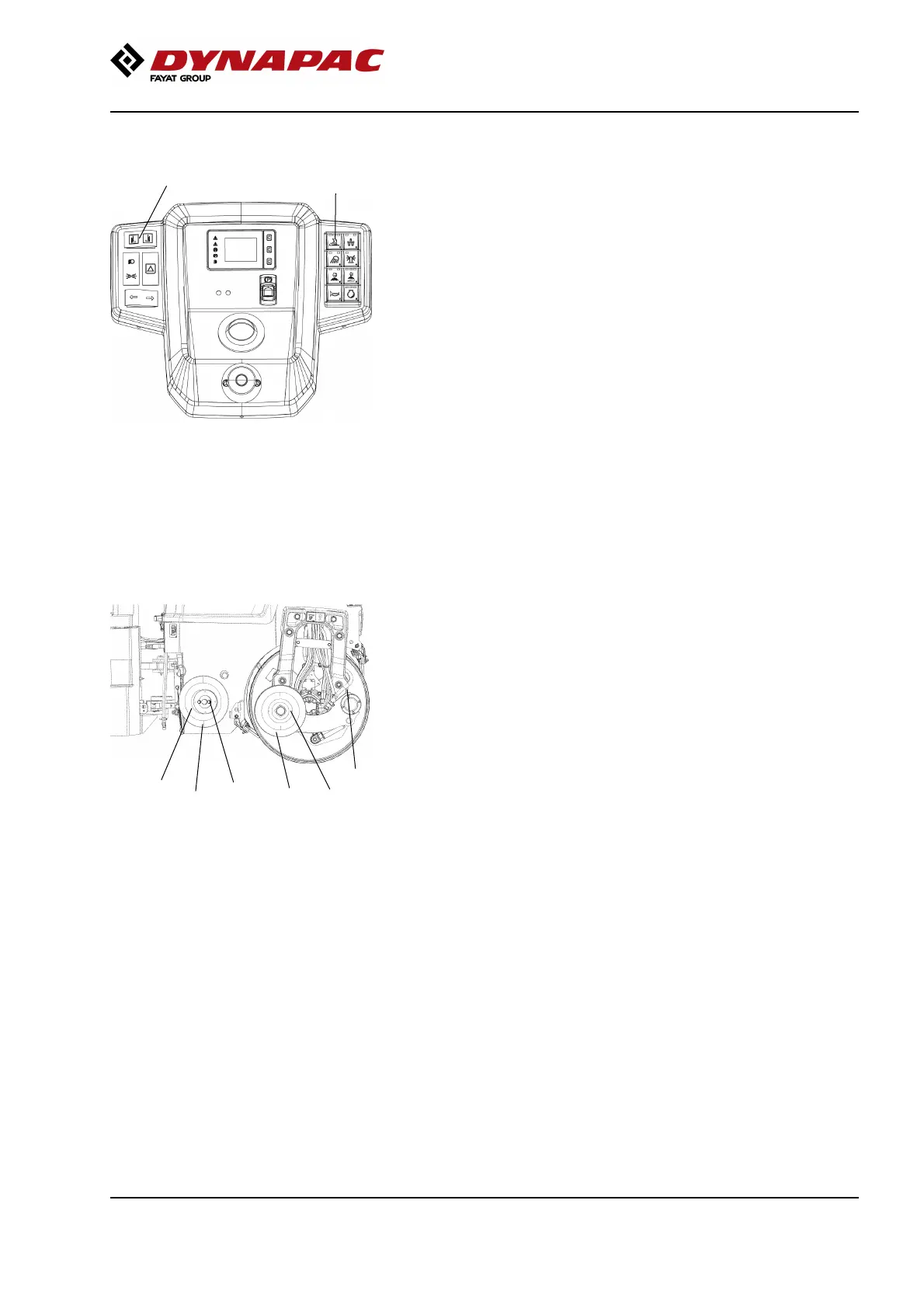
5
Fig. Changing tools
1. Edge compactor
2. Edge cutter
3. Bolted joints
4. Holder for cutter/compactor wheel
5. Ball valve
4
3
3
1
2
The operator can choose between two tools, the edge
cutter or edge compactor. The edge cutter (1) in the
figure is shown in the operating position. The edge
compactor (1) can easily be replaced with the edge
cutter by releasing the bolted joint (3).
77
 Loading...