17
OPERATION
2.6 Dashboard
Operation_Pic_number:1
Text-module
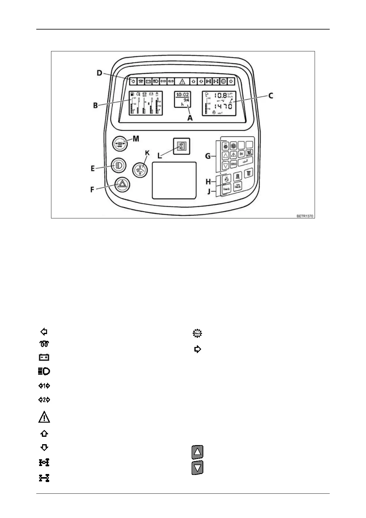
Fig.7
A = Multiple display
B = Indication of fluid levels
C = Operating status display
D = Indicator lamps
E = Lights including side lights
F = Hazard warning flasher switch
G = Key pad for on-board computer (also
see OPERATION Section 26).
H = Key pad for rpm indicators (also see
OPERATION Section 2.8).
J = Key pad for speed display (also see
OPERATION Section 2.8).
K = Emergency mode (also see FAULTS
AND REMEDIAL ACTIONS Section 6).
L = Alternator 1 not charging, red.
M = Hydraulic trailer brake (optional), (see
also OPERATION Section 15.3).
Text-module
Left turn signal indicator, green.
Preheater indicator lamp, red.
Alternator 2 not charging, red.
High beam, blue.
1st trailer light indicator, green.
2nd trailer light indicator, green.
Hazard light, red.
Forward direction of travel, green.
Reverse direction of travel, green.
4-WD engaged, green.
Differential lock engaged, red.
Text-module
Automatic dimmer
for forward/reverse indicator lamps, 4-WD, diffe-
rential lock and related buttons.
At dusk or in the dark, the dimmer can be adju-
sted manually.
Cruise control on.
Right turn signal indicator, green.
If one of the indicator lamps for forward/reverse
fails, back-up indicators can be activated on the
multiple display (A) activation (see see
OPERATION Section 26.5).
Brightness is increased or decreased by
pressing one of the two buttons.
 Loading...