5.1 SUMMARY OF DIAGNOSTIC POSSIBILITIES
The modular valve terminal offers extensive and
user-friendly possibilities of diagnosis and error
treatment. Depending on the equipment fitted,
the following possibilities are available:
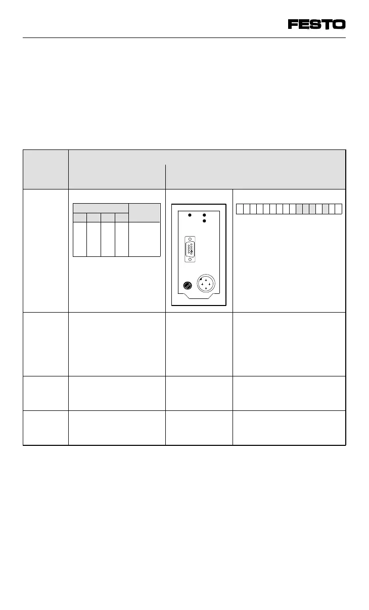
Equipment on the valve terminal
Input modules
(electrical inputs)
FB13
Dia-
gnostic
possi-
bilities
Status bits
X = not relevant
LEDs Diagnostic word
Brief
descrip-
tion
The four status bits
are transferred to the
field bus module
cyclically as "inputs"
with the normal inputs.
The LEDs
show
configuration
error,
hardware error,
bus error etc.
The diagnostic word must
be user-program
controlled (acyclically)
read, and evaluated.
Advan-
tage
Fast access to error
messages
Fast "on-the-
spot" error
recognition
Detailed error recognition
Detailed
descrip-
tion
Chapter 5.4 Chapter 5.2 Chapter 5.5
Fig. 5/1: Possibilities of diagnosis and error treatment
Statusbits Bedeutung
Bit 7 Bit 6 Bit 5 Bit 4
0
X
X
X
1
X
0
0
1
1
X
X
0
1
0
1
X
X
0
X
X
X
X
1
7654321076543210
VIFB13 - 03/05 5. Diagnosis/error treatment
9701 NH 5-3