Type 03: Description of components
Valve terminal type 03 consists of individual
modules. Each module is designed with different
functions, connections, display and operating
elements as shown below.
3
2 4 51
4
6
55
44
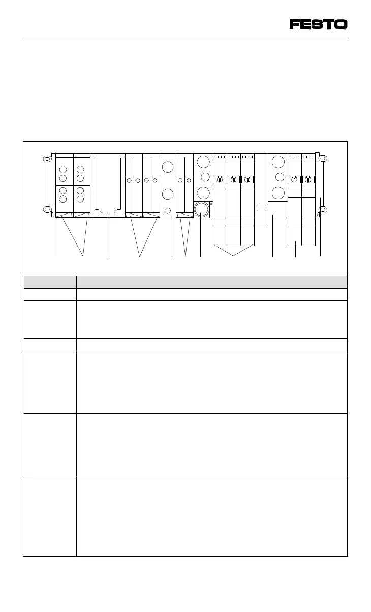
Fig. 1/2: Modules of valve terminal type 03
Figure Meaning
1 Node FB9
2 Electric modules (input/output modules), fitted with
• digital inputs (modules with 4 or 8 inputs)
• digital outputs (modules with 4 outputs)
3 End plate left with hole for additional earth cable connection
4 Pneumatic modules (valve sub-bases) fitted with S valves:
• 5/2 single solenoid valves
• 5/2 double solenoid valves
• 5/3 mid-position valves (exhausted, pressurized, blocked)
• blanking plates S = Auxiliary pilot air
5 Pneumatic MIDI or MAXI modules:
• pressure supply with integrated exhaust (MIDI)
• intermediate air supply with integrated exhaust (MIDI)
• pressure supply adapter with/without regulator (MIDI/MAXI)
• additional air supply module (MAXI)
6 End plate right, depending on the size of the last sub-base:
• with common pneumatic tubing connections and integrated
regulator for 5 bar auxiliary pilot air
(unregulated pilot air is not permitted)
• with common pneumatic tubing connections, but without
integrated regulator
• without common pneumatic tubing connections (only MAXI)
VIFB13 - 03/05 1. User instructions
9701 NH 1-5