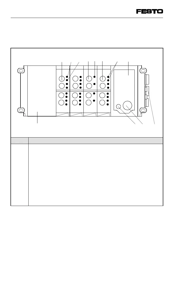
The following connection and display elements
are to be found on the electric modules:
No. Meaning
1
2
3
4
5
6
7
8
9
10
11
12
Output socket for electrical output
Yellow LED (status display per output)
Red LED (error display per output)
Input socket for one electrical input
Green LED (per input)
Input socket for two electrical inputs
Two green LEDs (one LED per input)
Node with LEDs and field bus interface,
detailed description in Chapter "Installation"
Right-hand end plate
Operating voltage connection
Fuse for inputs/sensors
AS-i master for I/O periphery; analogue I/Os; further modules
1 2 3
4
56
7 8
11
10
9
O4 O4
I4
I8
12
AS-i
master;
analogue
IOs
Fig. 1/3: Display and connection elements of the electronic modules
VIFB13 - 03/05 1. User instructions
1-6
9701 NH