Configuring the valve terminal
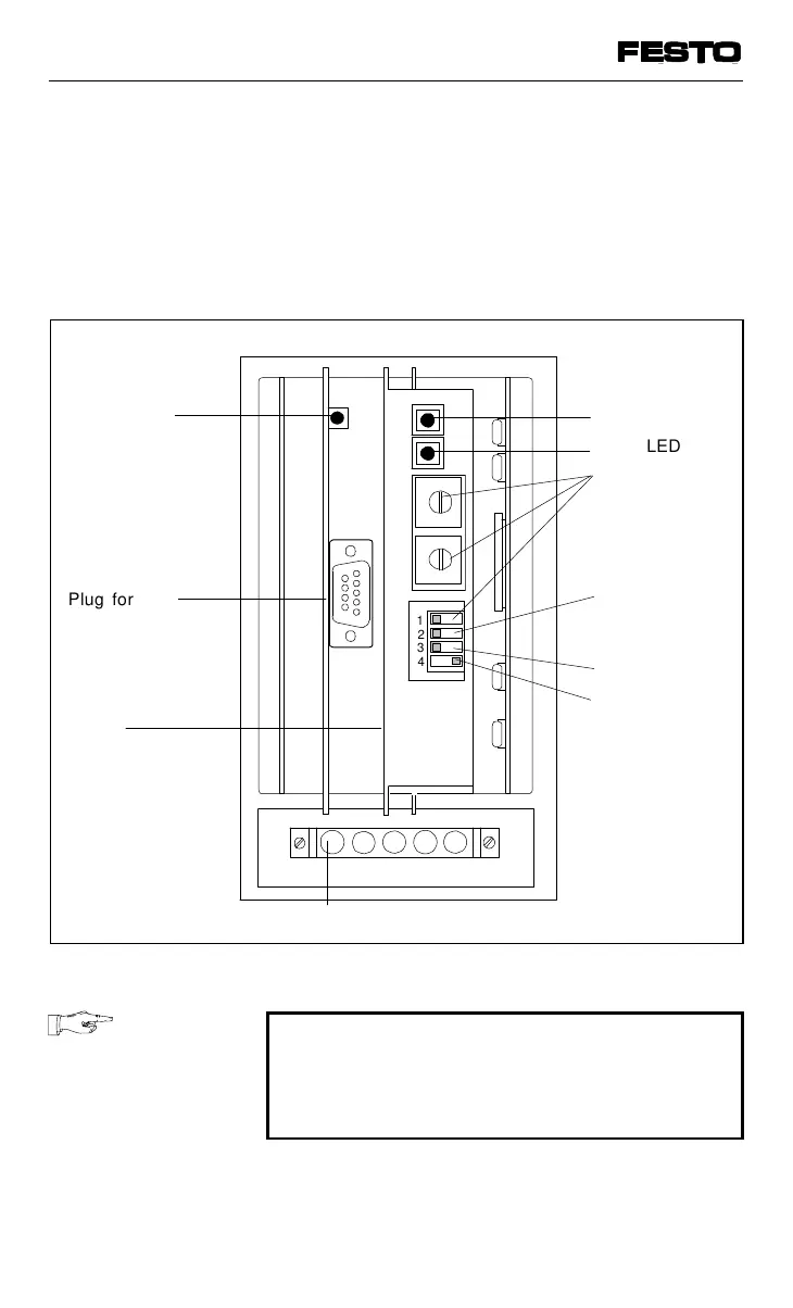
There are four PC boards in the node. Board 2
contains an LED and a plugs for the cables.
Board 3 contains two LEDs and switches for
setting the configuration.
PLEASE NOTE
Boards 2 and 3 are connected with each
other. They can only be removed or inserted
together.
1
2
3
4
A
Plug for field
bus cables
Address
selector
switches
(station
number)
Shield
Reserved
Plug for operating voltage connection
Green LED
Reserved
Voltage
monitoring
on/off
Fig. 3/3: Connection, display and operation elements of the node
VIFB13 - 03/05 3. Installation
9701 NH 3-9