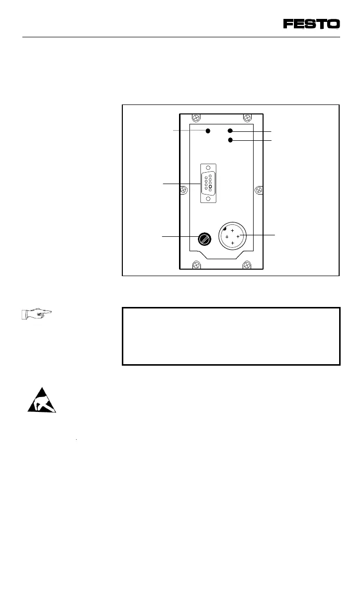
The following connection and display elements
are to be found on the cover of the node:
PLEASE NOTE
The cover is connected to the internal PC
boards via the operating voltage cable. It can-
not therefore be removed completely.
• Opening
Unscrew the 6 Philips screws in the cover
and carefully remove the cover by lifting
upwards. Do not damage the cable through
mechanical stress.
• Closing
Replace the cover. Place the cables for the
operating voltage connection back into the
housing so that they are not clamped. Tighten
the Philips screws in the cover in diagonally
opposite sequence.
Green LED
Fuse for
power
supply to
inputs
Plug for
field bus
cable
Power supply
connection
Fig. 3/2: Cover of the node
VIFB13 - 03/05 3. Installation
3-8
9701 NH