3.3 CONNECTING THE PROFIBUS DP INTERFACE
PLEASE NOTE
Only the Festo plug will fulfill requirement
IP 65.
There is a sub-D connection on the node for
connecting the CP system to the PROFIBUS-
DP. This connection is used for the incoming
cable, as well as for the continuing fieldbus
cable. The node can be connected with the
sub-D plug from Festo (part no. 18529).
Outer diameter of cable for Festo Sub-D plug:
6 .. 9 mm.
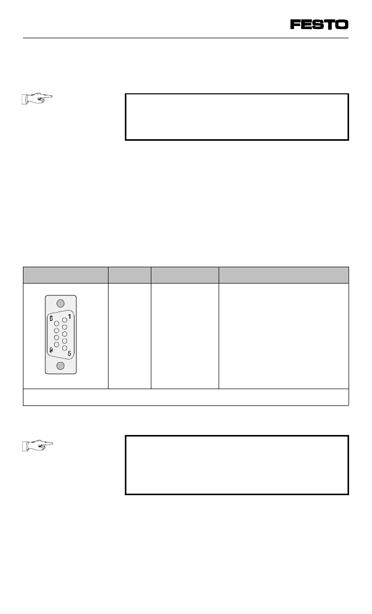
Pin assignment Pin Signal Designation
1
2
3
4
5
6
7
8
9
Housing
n.c.
n.c.
RxD/TxD-P
CNTR-P
1
DGND
VP
n.c.
RxD/TxD-N
n.c.
Screening
Not connected
Not connected
Receive/send data-P
Repeater control signal
Data reference potential (M5V)
Positive power supply (P5V)
Not connected
Receive/send data-N
Not connected
Direct connection to the housing
1
Repeater control signal CNTR-P is produced as a TTL signal.
Fig. 3/16: Connecting the PROFIBUS DP interface
PLEASE NOTE
Before connecting Sub-D plugs of other manu-
facturers, you must replace both flat screws by
bolts (part no. 340960).
VIFB13 - 03/05 3. Installation
9701 NH 3-29