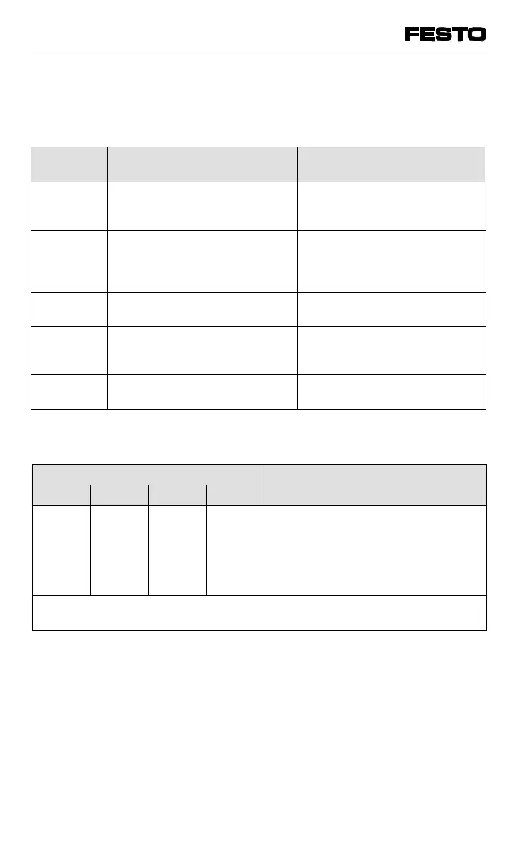
The diagnostics information of the four status
bits is coded and has the following meaning:
* Only if voltage monitoring is activated (see chapter 3.2, DIL switches)
Diagnostic
information
Meaning Cause
V
valves
*
(V
val
)
Monitors the tolerance of the
operating voltage of the valves
and electrical outputs.
Operating voltage at pin 2 of
operating voltage connection
< 21.6 V
V
outputs
*
(V
out
)
Monitors the operating voltage
of the valves and electrical
outputs (no voltage available
e.g. EMERGENCY STOP).
Operating voltage at pin 2 of
operating voltage connection
< 10 V
V
sensors
(V
sen
)
Monitors the supply voltage of
the inputs (sensors).
Internal fuse triggered
Short
circuit/
overload
Monitors the electrical outputs
of the output modules.
Short circuit
or
overload
A-Bit Diagnostic information on
AS-i/analogue I/O modules
Error on AS-i or hardware
error on analogue module
Fig. 5/9: Error states of valve terminal
Bit number*) Meaning
X = not relevant
2
7
2
6
2
5
2
4
0
X
X
X
1
X
0
0
1
1
X
X
0
1
0
1
X
X
0
X
X
X
X
1
No error
Output: short circuit/overload
V
valves
<
21.6 V*
Voutputs
< 10 V*
V
sensors
< 10 V
A-Bit (AS-i / analogue I/Os)
*) The status bits always address the four highest-value addresses of
the configured address range.
Fig. 5/10: Coded diagnostics information of the four status bits
VIFB13 - 03/05 5. Diagnosis/error treatment
9701 NH 5-13