Calculating with a formula
Proceed as follows:
1. Calculate the maximum current consumption
of the inputs and electronic components (I
1
)
as well as of the outputs/valves (I
2
).
2. Calculate the lowest voltage to be expected
on the power unit during operation (V
Omin
).
Take into consideration:
• the influence of load variation of the power
unit
• the fluctuations in the primary
mains voltage.
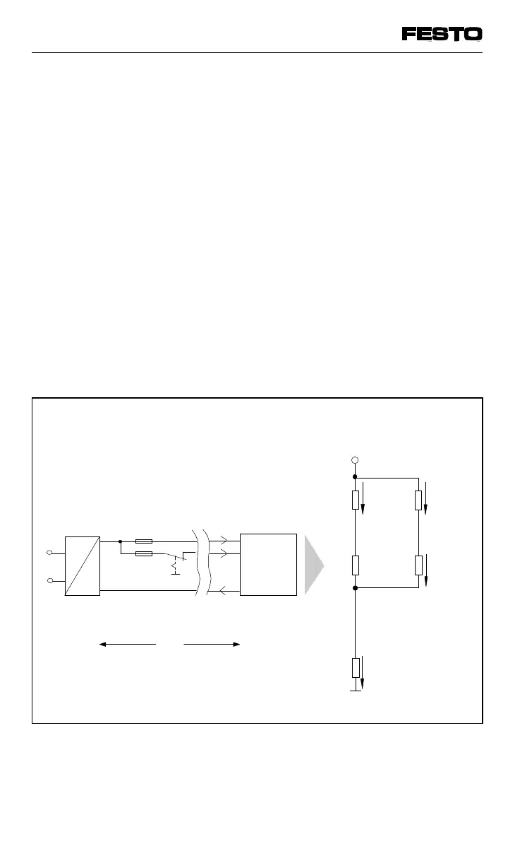
3. Enter the values in the appropriate formula.
The replacement circuit diagram and the
example explain the process.
AC
DC
0 V
V
B
EMERG. STOP
3.15 AT
10 AT
I
1
I
2
Pin 1
Pin 2
Pin 3
Valve
terminal
R
L0
0 V
V
L2
+ V
L1
Vterminal
R
I2
R
I1
V
B
R
L1
Line
resistance
(returning)
V
L1
V
L2
R
L2
Distance (cable length)
L
Operating voltage supply
Replacement circuit diagram
I
0
Fig. A/3: Cable length (L) and line resistance (R
L)
VIFB13 - 03/05 Appendix A
A-10
9701 NH