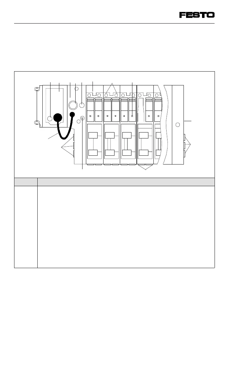
The connections, display and operating elements
shown below are to be found on the ISO
modules of type 05.
No. Meaning
1
2
3
4
5
6
7
8
9
10
11
12
Node with LEDs and field bus interface, detailed description see
chapter "Installation"
Fuse for inputs/sensors
Adapter module
Operating voltage connection of valve terminal type 05
Fuse for valves
Valve location inscription field
Yellow LEDs (per pilot solenoid)
Manual override (per pilot solenoid, pushing or locking)
Connection for external pilot air
Common connections
Work connections (per valve)
Adapter cable for operating voltage of node and I/O modules
Fig. 1/7: Operation, display and connection elements of
ISO modules type 05
The electronic modules are described in this
chapter, "Description of components type 03".
10
12
9
9
10
6
745
2
3
1
VIFB13 - 03/05 1. User instructions
1-10
9701 NH