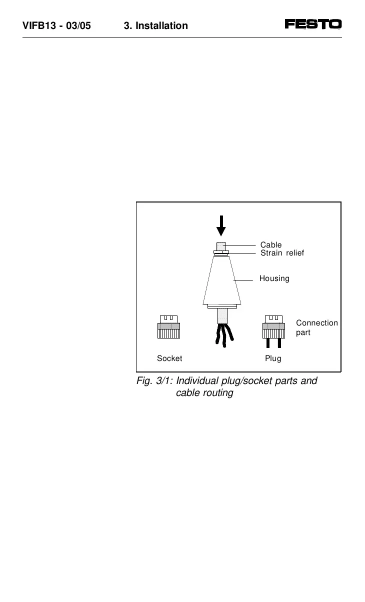
2. Open the strain relief on the rear part of the
housing. Pass the cable through as shown in
the diagram below (PG = Conduit thread).
Cable diameter:
PG 7: 4.0 ... 6.0 mm
PG 9: 6.0 ... 8.0 mm
PG 13.5: 10.0 ...12.0 mm
Plugs/sockets (straight/angled):
Power supply socket: PG 7, 9 or 13.5
Sensor plug: PG 7
3. Remove 5 mm of insulation from the
end of
the cable.
4. Fit the strands with cable end sleeves.
5. Connnect the ends of the cables.
6. Insert the connection part onto the housing
of the plug/socket again. Pull the cable back
so that it is not looped inside the housing.
7. Tighten the strain relief.
AA
AA
AA
AA
AA
AA
AAA
AAA
AA
AA
AAA
AA
AAA
AAA
AA
AA
AAA
AA
Strain relief
Socket
Fig. 3/1: Individual plug/socket parts and
cable routing
VIFB13 - 03/05 3. Installation
3-6
9701 NH