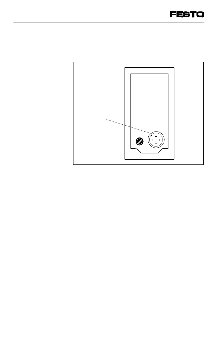
The 24 V operating voltages are connected at
the lower right-hand edge of the node.
The following + 24 V DC supplies are made via
this connection:
• the operating voltage for internal electric
components and the power supply to the
inputs of the input modules
(pin 1: DC 24 V, tolerance ± 25 %; external
fuse recommended max. 3.15 A).
• the operating voltage for the outputs of the
valves and the outputs of the output modules
(pin 2: DC +24 V, tolerance ± 10 %; external
fuse max. 10 A required).
Recommendation
The operating voltage for the outputs should
be connected via the EMERGENCY STOP
circuit.
Operating
voltage
connection
Fig. 3/8: Operating voltage connection
VIFB13 - 03/05 3. Installation
3-16
9701 NH