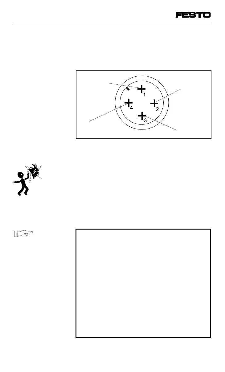
The following diagram shows the pin assignment
of the operating voltage connection on the
adapter plate.
Protective earthing
The valve terminal has two protective earth
connections:
• at the operating voltage connection
(pin 4, incoming socket)
• at the left-hand end plate (M4 thread).
PLEASE NOTE
•
Always connect the earth cable to pin 4 of
the operating voltage connection.
•
Make sure that the housing of the valve
terminal and the earth cable at pin 4 have
the same potential and that no equalizing
currents flow.
•
Connect an earth cable of sufficient cross-
section to the left-hand end plate if the
valve terminal is not mounted on an earthed
machine stand.
In this way you can avoid interference due to
electromagnetic sources.
0 V
PE
(protective earth
connection, leading contact)
24 V supply
for electronic
components
and inputs
24 V supply for
valves, outputs
Fig. 3/14: Pin assignment of the operating
voltage connection
VIFB13 - 03/05 3. Installation
3-26
9701 NH