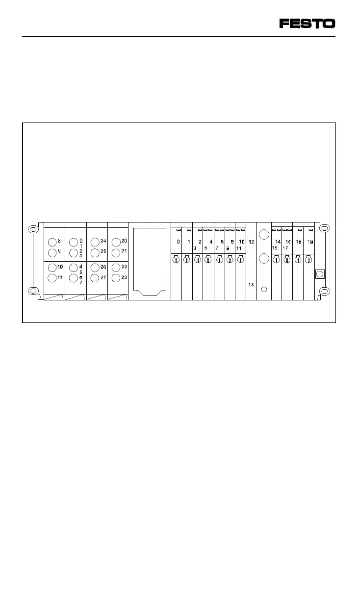
The diagram below shows the modifications to
the address assignment in the example of an
extension to the standard fitting shown in the
previous diagram.
Air supply modules and intermediate air supply
modules do not occupy any addresses.
4-input module
8-input module
4-output module
4-output module
S-type sub-base
D-type sub-base
Do not round up
D-type sub-base
D-type sub-base
D-type sub-base
S-type sub-base
Intermediate air supply
Fig 4/5: Address assignment of a valve terminal after extension/
conversion
VIFB13 - 03/05 4. Commissioning
9701 NH 4-17