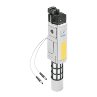
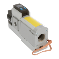
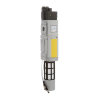
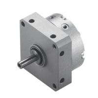
1. Summary of components
1-9
Festo P.BE-SPC11-SYS-ASI-EN en 0203NH
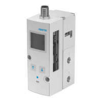
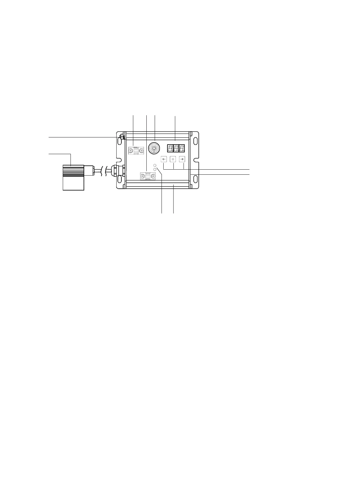
1.3 Display and connecting elements on the SPC11
The diagram below shows the display and connecting
elements of the SPC11.
12 3 4
5
6
7
8
9
aJ
1
24 V DC: Operating voltage connection
2 Bus: AS-Interface bus connection for
coupling to a PLC/IPC
3 Valve: Valve connection
4 Display
5 Operating buttons
6 Type plate see side
7 Groo ve for identification signs
(type I BS 6x10)
8 ASI LED (bus status, green),
Fault LED (fault, red)
9 Measuring system connection
aJ Earth/ground connection
Fig. 1/3: Display and connecting elements of the SPC11

 Loading...