1. Summary of components
1-7
Festo P.BE-SPC11-SYS-ASI-EN en 0203NH
1.2 Method of operation
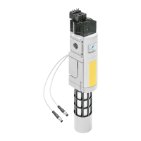
Tasks of the SPC11 The SPC11 takes o ver the following tasks:
– It ascertains characteristic system values of the con-
nected components.
– It saves the desired end positions and intermediate
positions.
– It specifies the end positi ons and intermediate positions.
– It compares the nominal and actual positions and controls
positioning by appropriate actuation of the proportional
directional control valve (status control).
Method of operation The SPC11, the valve, the drive and the measuring system
are connected together to form a closed-loop control circuit.
In this closed-loo p control circuit, the position of the move-
able mass represents the control variable. This type of con-
trol circuit is therefore also called positioning control.
In the following text, the term “moveable mass” also repre-
sents the terms piston, slide and flange shaft.
The following diagram shows the basic layout of a positioning
control circuit with the SPC11.

 Loading...