2 Operator‘s Manual for instrument types MP0R
Instrument Description
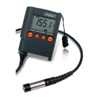
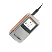
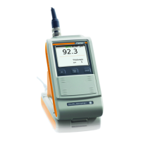
1.2 Components
1.3 Display symbols
Front view
(ins tru ment model MP 0R il l ustr ated)
Rear view
Please Note!
Remove the battery
contact foil before first use.
Symbols Explanation
Indicates the data transfer.
Indicates low battery power.
Indicates the active lock function for the calibration/normal-
ization.
NFe The measurement uses the eddy current test method, mag-
netic base material is necessary.
Fe The measurement uses the magnetic induction test method,
non-magnetic metal base material is necessary.
µm, mils Unit of measurement for the displayed reading.
,
Indicates the violation of the set specification limits.
1 S i gna l LE D f o r m e a-
sur em e nt ac ce pt ;
re d: l i m i t vi ol a t i on,
gr een : ok
2 W ri st strap
3 D isplay on the top
4 D isplay on the front
5 Function keys
6 USB connector
7 Pl aceme nt support
8
MP0R
: Probe w it h orange
protect ion cap
MP0R-FP/MP0RH- FP
:
Probe connect ed wi th
cable
9
Protection cap
9 Battery compartment cover