FISCHER Mess- und Regeltechnik GmbH Operation | 5
BA_EN_DE90 65
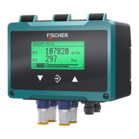
The following colour change red/yellow/green is examined as an example for all
colour changes. There are a total of four switch thresholds (S1...S4) in which a
colour change is realised. This leads to the following image without hysteresis.
Risk level
Switching thresholds
Measuring range
RED REDYELLOW YELLOWGREEN
2 1 0 1 2
S1 S2 S3 S4
Fig.88: Colour change (without hysteresis)
The parameter Col.ch. C1 hyst. defines a distance to the switch threshold.
The colour change with hysteresis is then realised as follows:
(i) Lower switching thresholds S1 and S2
In case of a colour change from a higher to a lower risk level, the hysteresis
acts with an increasing signal.
S1
+ 0.5
Increasing signal
Falling signal
Fig.89: Example: Hysteresis S1
(ii) Upper switching thresholds S3 and S4
In case of a colour change from a lower to a higher risk level, the hysteresis
acts with an decreasing signal.
S4
-0.5
Increasing signal
Falling signal
Fig.90: Example: Hysteresis S4
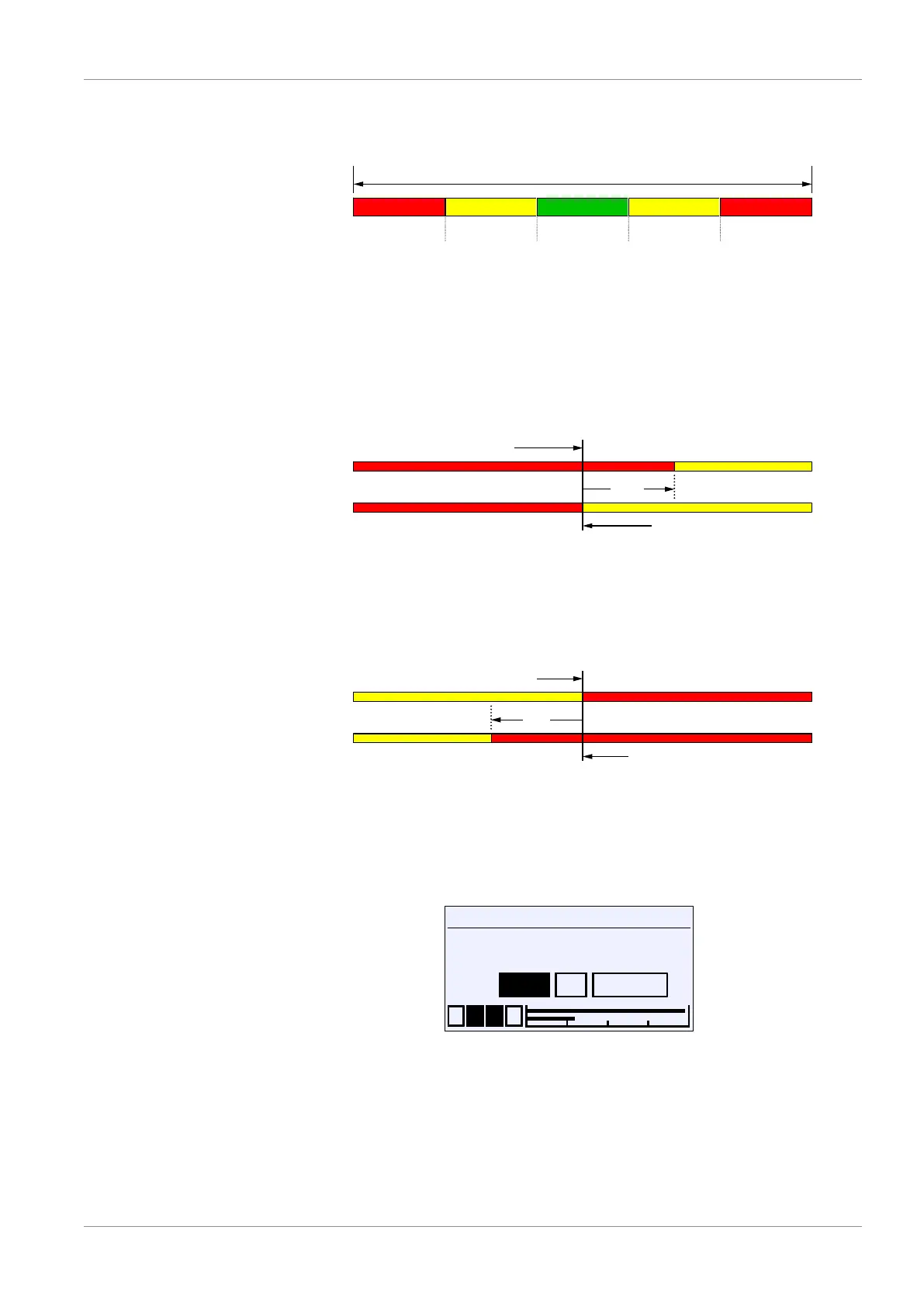
5.5.1.5.4 Colour change C1 delay on
Directory: \Configuration\Channel 1\Colour change C1\Col.ch. C1 delay on
Level 4:
Col.ch. C1 delay on
1 2 3 4
OK CancelEdit
0
s
U
Fig.91: Colour change C1 delay on
The activation delay acts when changing from a lower risk level to a higher risk
level.