5 | Operation FISCHER Mess- und Regeltechnik GmbH
64 BA_EN_DE90
For example:
Channel 1: Basic measuring range: 0 … 100 Pa
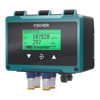
The measuring range is defined as 10 … 90 Pa. The green range should be 0
… 60 Pa. Then the critical range (yellow) up to 70 Pa starts. This is where the
red range that ranges up to the measuring range end at 90 Pa starts. The lower
colour changes red-yellow and yellow-green are switched off.
Basic measuring range
MES3 S4MS
S1
S2
REDYELLOWGREEN
0
100 Pa
10 60 70 905
Fig.86: Example colour-change red/yellow/green
MS Meas.range C1 start 10 Pa
S1 Col.ch. C1 red-ylw 5 Pa < MS
S2 Col.ch. C1 ylw-grn 5 Pa < MS
S3 Col.ch. C1 grn/ylw 60 Pa
S4 Col.ch. C1 ylw/red 70 Pa
ME Ms.range C1 end 90 Pa
The lower colour changes S1 and S2 are 'switched off' by placing thresholds
outside the measuring range. If the threshold values were to be laid precisely at
the start of the measuring range, the display would shine red in the zero-point,
Red > Yellow > Green The cause for this lies in the priority of the colours. The red colour has priority
over the yellow colour and this has priority over the green colour.
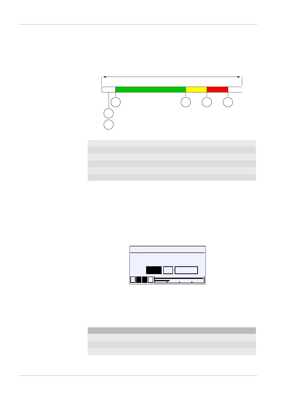
5.5.1.5.3 Colour change C1 hysteresis
Directory: \Configuration\Channel 1\Colour change C1\Col.ch. C1 hyst.
Level: 4
Col.ch. C1 hyst.
1 2 3 4
OK CancelEdit
10.000
Pa
U
Fig.87: Colour change C1 hyst.
This parameter can be used to define an hysteresis for the switch thresholds of
the colour change. The set hysteresis applies to all switch thresholds at the
same time. The input is a pressure value in the current unit. The allowed value
range is stated automatically.
Functional principle: The colour symbolises the following risk levels:
Colour Risk level Operating mode
Green 0 Normal
yellow 1 Warning
rot 2 Danger