Flexball Italiana S.r.l. 33
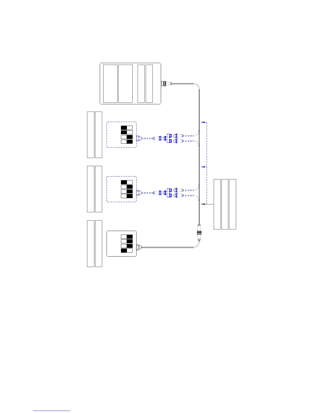
7.4. Installation with 1 actuator – solution D
The actuator is placed at one end of the CANBus network.
Cod: 3500.33-*****
Data transmission cable
Cavo di trasmissione dati
Actuator
Attuatore
4321 4321 4321
JP19: YES (end-line)
JP14: NO (address)
1st command station
1a stazione di comando
2nd command station
2a stazione di comando
3rd command station
3a stazione di comando
This installation scheme is valid for systems with:
• up to 3 command stations and 1 engine with mechanical throttle, mechanical gearbox, with/without trim
(or flap);
• up to 3 command stations and 1 hybrid engine with mechanical throttle, mechanical gearbox, analogue
outputs for electric engine inverter driven, with/without (or flap);
• up to 3 command stations with 1 or 2 mechanical throttles and 1 or 2 solenoid gearboxes, analogue
outputs for electric engine inverter driven, with/without (or flap);
• up to 3 command stations and 1or 2 engines with electronic throttle (voltage or CANBus), mechanical
gearbox, with/without trim (or flap);
• up to 3 command stations and 1 or 2 engines with electronic throttle (voltage or CANBus), solenoid
driven gearbox, with/without trim (or flap);
• up to 3 command stations and 1 or 2 hybrid engines with electronic throttle (voltage or CANBus),
mechanical gearbox, analogue outputs for electric engine inverter driven, with/without trim (or flap);
• up to 3 command stations and 1 or 2 hybrid engines with electronic throttle (voltage or CANBus),
solenoid driven gearbox, analogue outputs for electric engine inverter driven, with/without trim (or flap).
 Loading...