Flexball Italiana S.r.l. 64
20. Programming of actuators with the option for hybrid motors
The interface towards the hybrid motors is through a voltage signal produced by the actuator. The actuator can
generate 2 voltage signals per each motor. Usually the second channel is used as speed reference for the
frequency converter which drives the electrical motor.
This programming section is an addendum with respect to the programming instructions for the basic actuators
described from section 13. to 18. included.
Description of the cables between actuator and frequency converter is reported at section 6.2. Wiring scheme
connections are described at section 10.2
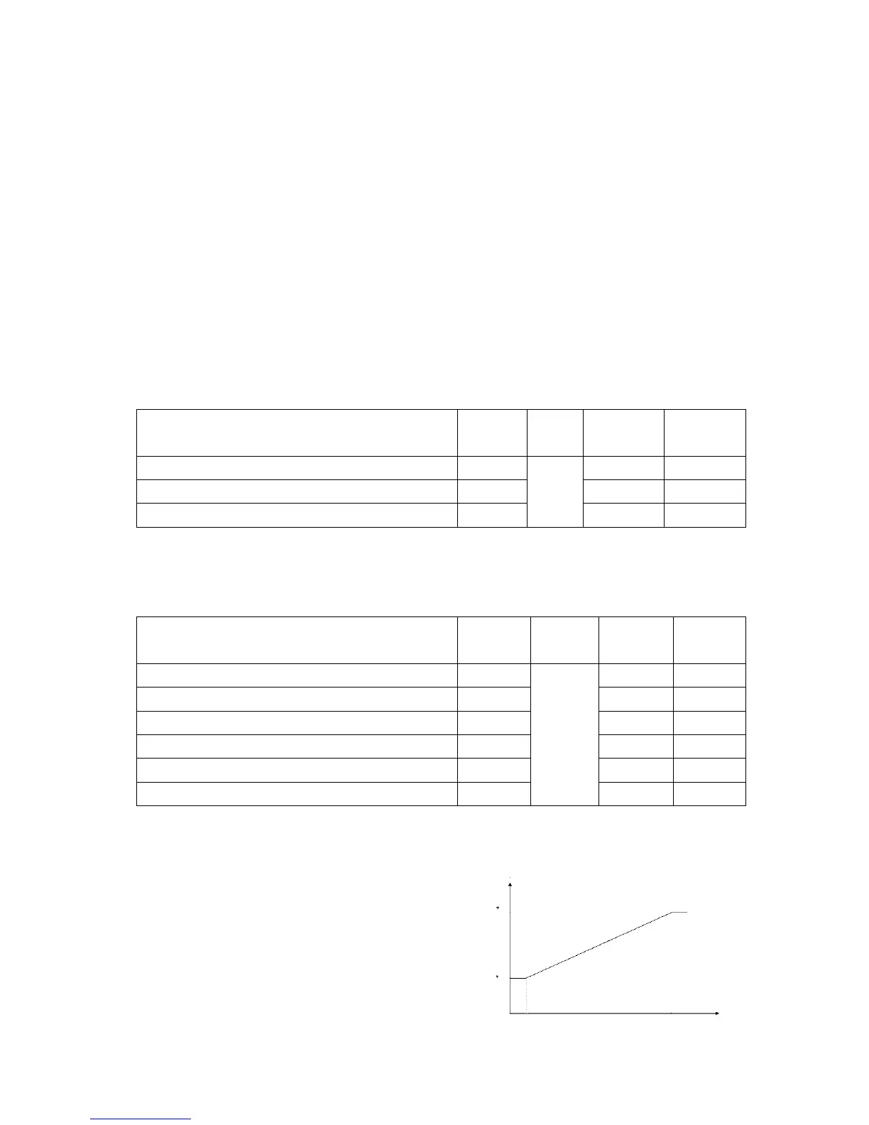
In order to produce the voltage profile as reported in the diagram here below, you need to define minimum and
maximum voltage. These values are defined through parameters L*, H* and C*.
Parameters setting for installations with 1 motor
Display Range
Factory
setting
Value on
display
Throttle minimum voltage channel 2 L2 0,0 0
Throttle maximum voltage channel 2 H2 5,0 50
Starting acceleration point on channel 2 C2
0 – 5
Vdc
0,0 00
Parameters setting for installations with 2 motors
Display Range
Factory
setting
Value on
display
Throttle minimum voltage channel 2 left motor L2 0,0 0
Throttle maximum voltage channel 2 left motor H2 5,0 50
Starting acceleration point on channel 2 left motor C2 0,0 00
Throttle minimum voltage channel 4 right motor L4 0,0 0
Throttle maximum voltage channel 4 right motor H4 5,0 50
Starting acceleration point on channel 4 right motor C4
0 – 5
Vdc
0,0 00
change of factory setting might
cause a wrong functioning of the system! It is
therefore recommended to do not make any
change without previously contacting the producer.
 Loading...