Flexball Italiana S.r.l. 34
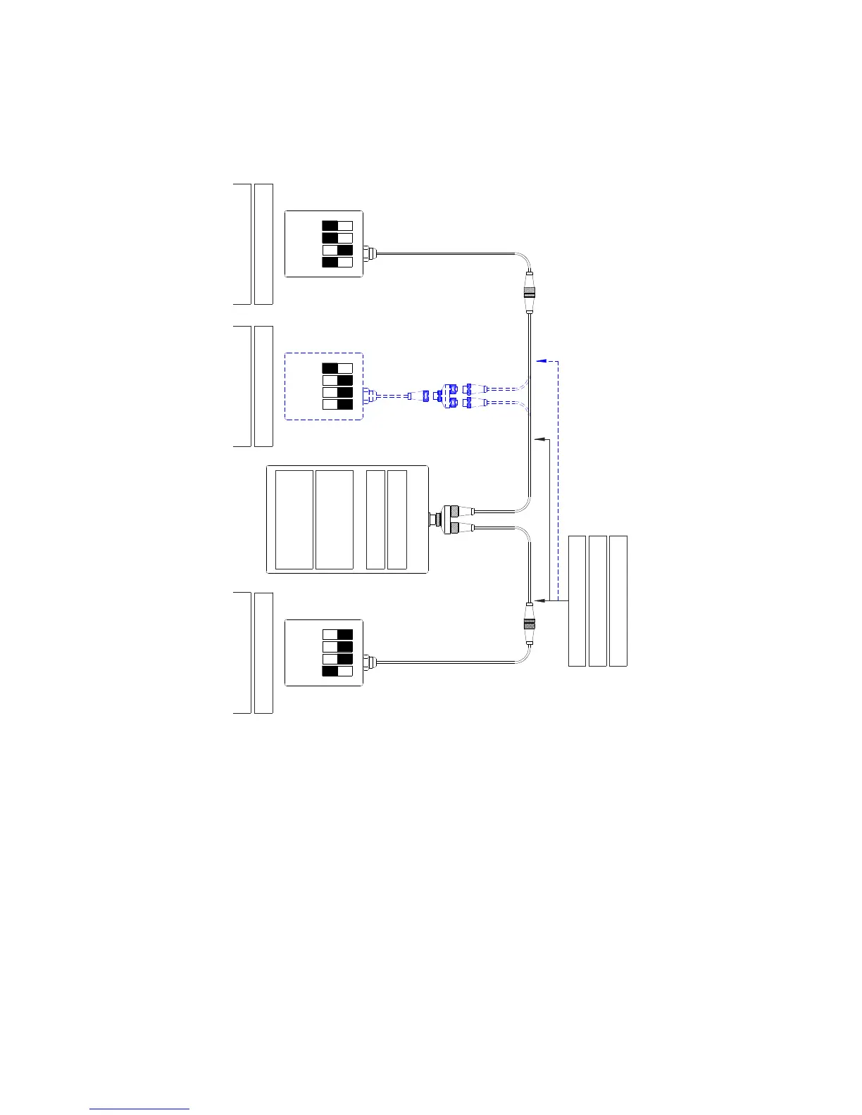
7.5. Installation with 1 actuator – solution E
The actuator is placed in the middle of the CANBus line.
1st command station
1a stazione di comando 3a stazione di comando
3rd command station 2nd command station
2a stazione di comando
432143214321
JP14: NO (end-line)
JP14: NO (address)
Actuator
Attuatore
Cod: 3500.33-*****
Data transmission cable
Cavo di trasmissione dati
This installation scheme is valid for systems with:
• up to 3 command stations and 1 engine with mechanical throttle, mechanical gearbox, with/without trim
(or flap);
• up to 3 command stations and 1 hybrid engine with mechanical throttle, mechanical gearbox, analogue
outputs for electric engine inverter driven, with/without (or flap);
• up to 3 command stations with 1 or 2 mechanical throttles and 1 or 2 solenoid gearboxes, analogue
outputs for electric engine inverter driven, with/without (or flap);
• up to 3 command stations and 1or 2 engines with electronic throttle (voltage or CANBus), mechanical
gearbox, with/without trim (or flap);
• up to 3 command stations and 1 or 2 engines with electronic throttle (voltage or CANBus), solenoid
driven gearbox, with/without trim (or flap);
• up to 3 command stations and 1 or 2 hybrid engines with electronic throttle (voltage or CANBus),
mechanical gearbox, analogue outputs for electric engine inverter driven, with/without trim (or flap);
• up to 3 command stations and 1 or 2 hybrid engines with electronic throttle (voltage or CANBus),
solenoid driven gearbox, analogue outputs for electric engine inverter driven, with/without trim (or flap).
 Loading...