5 – X-series Camera Controller
X-series User’s Manual
46
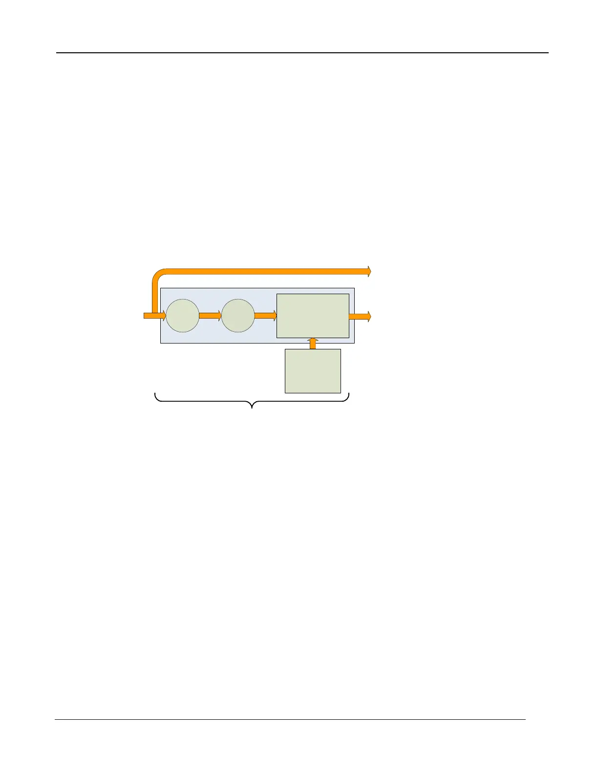
5.4.3.1.3 Update Offset
Often times during the normal operation of a camera the electronics and/or optics will heat up or cool
down which changes the uniformity of the camera image. This change requires a new NUC.
However, this change is mainly in the offset response of the image while the gain component stays
constant. An Update Offset simply computes a new offset coefficient using the existing gain
coefficient and corrects the image non-uniformity. Update Offsets are typically performed when a
Two-Point NUC table is being used.
An Update Offset requires only one uniform source, usually set at a temperature on the lower edge of
the operational range.
5.4.3.1.4 Bad Pixel Correction
Within the NUC table there is an indication as to whether or not a pixel has been determined to be
bad as shown below. There are two methods used to determine bad pixels.
Bad Pixel Correction
First, the NUC table gain coefficients are compared to a user defined acceptance boundary,
Responsivity Limit Low/High (%). The responsivity of a pixel can be thought of as the gain of that
pixel. The gain coefficient in the NUC Table is a computed value that attempts to correct the
individual pixel gain, or responsivity, to a normalized value across the array. Since the responsivity
value directly relates to the gain coefficient in the NUC table, the camera can scan the NUC table gain
coefficients and use them to determine if a pixel’s responsivity exceeds the limits as set by the user.
The second method of determining bad pixels is to search for twinklers. Twinklers are pixels that
have responsivity values within normal tolerances, but still exhibit large swings for small input
changes. These pixels are on the “verge” of being bad and often appear to be noisy. To find these
types of pixels the camera collects a number of frames and records the maximum and minimum
values across that sample set for each pixel. If the delta between max and min exceeds the Twinkler
max pixel value delta then the pixel is determined to be bad.
Since the responsivity test requires a gain coefficient, it is useless on NUC tables determine by the
One-Point Correction because those tables have a value of one (“1”) as the gain coefficients. The
Twinkler test can be done on either correction process.
The X-series camera uses the Nearest Neighbor algorithm for bad pixel replacement, a simple
replacement using an adjacent pixel. The adjacent pixel is picked using the pattern depicted below.
When a bad pixel is near an edge, those search positions are skipped.

 Loading...