5 – X-series Camera Controller
X-series User’s Manual
64
It is important to note the camera does not account for bad pixels when counting for saturation. When
determining the threshold, the user should account for the typical number of bad pixels.
5.4.3.10.1 Integrate Active Polarity
Sets the polarity (active high or low) of the Integrate Active signal on the camera rear chassis AUX
connector.
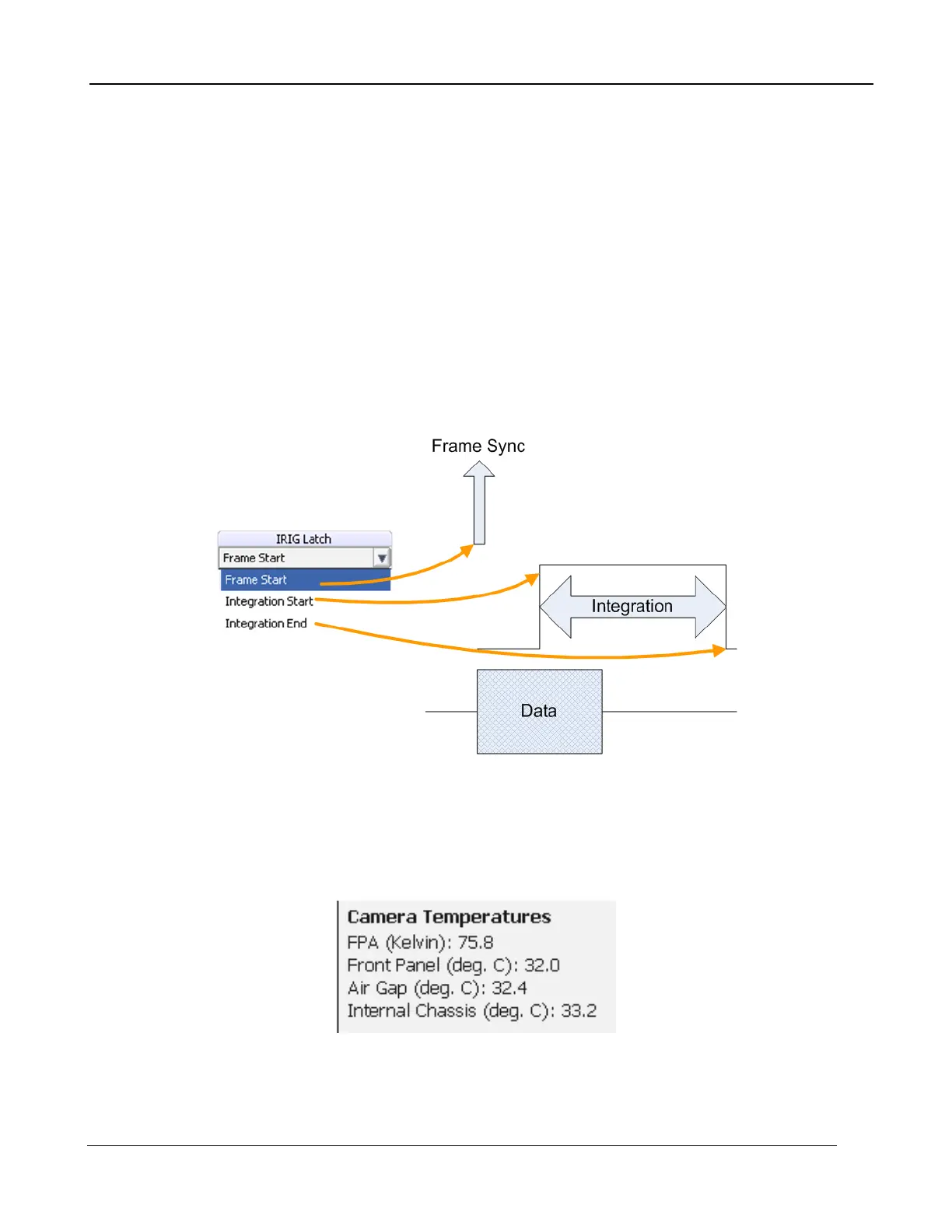
5.4.3.10.2 IRIG Latch
The X6900 and X8500 cameras place the IRIG time in the header for each frame of video. The
X6900 and X8500 can latch the IRIG data at the start of a frame, Frame Start, or in relation to the
integration time, Integration Start or Integration End. Depending on the frame process selected (see
Section 5.4.2.3.1.1) the Frame Start may indicate the time the integration starts or the time data is
being passed out the camera. Latching the IRIG time on Integration Start or End marks the time the
actual camera “exposure” occurred. The user should select the IRIG Latch value based on what
action within the camera they need to know the exact time of.
Figure 4-1: IRIG Latch Positions
5.4.3.10.3 Camera Temperatures
This part of the window displays the current temperature of the FPA, lens, and internal chassis temp
sensors. These values are automatically updated every few seconds. If all the values are not visible,
drag the corner of the controller window to make it larger.

 Loading...