Limitorque
®
Master Station IV EEP-SN4001 FCD LMENIM5010-00-AQ – 03/19
38
In standard mapping mode, the Function Code 02 mapping is a static mapping of the total input table as shown in Table
8.1 per MOV. A total of 80 bits represent an individual MOV. The use of this function code will provide the user with the
input status bits that are used to develop holding registers 9 through 13. Only the enabled bits will be returned as valid
data (otherwise, zeros). Address affect is accounted for in the MSIV decoding process (i.e. 10,000). The A/B mapping
style operates similarly but with the exception that only enabled bits return data. So where the Standard Style returns all
bits, valid or not, A/B Style returns only the bits that are selected.
Table 7.1 – Status Bit Definitions
Bit Number Modbus Bit Address MX/DDC
129 128 Opened
130 129 Closed
131 130 Stopped in mid-travel
132 131 Opening
133 132 Closing
134 133 Valve jammed
135 134 Not in remote
136 135 Combined fault
137 136 Over-temperature fault
138 137 Actuator in Stop Mode
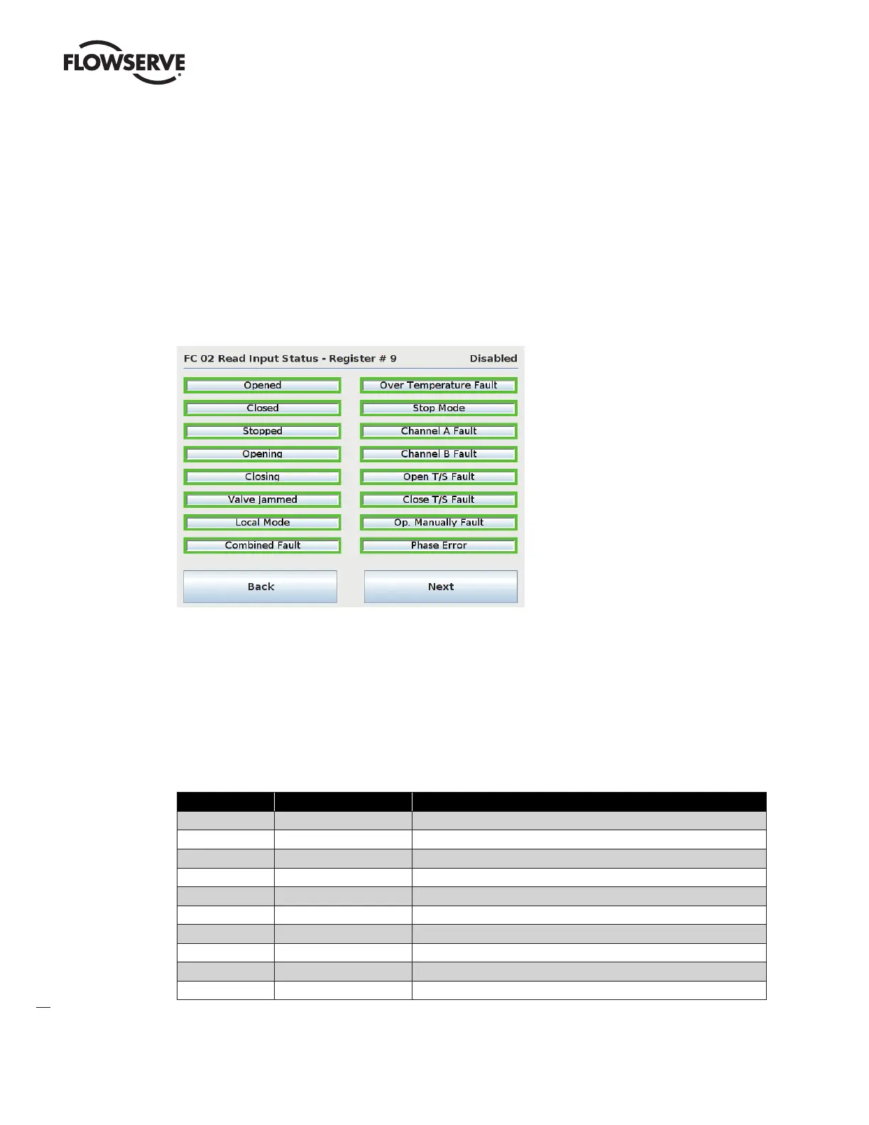
7.2.5.3.1 Modbus FC 02 Read Input Status
Pressing the “Modbus FC 02 Read Input Status” button will take the user to the FC 02 Read Input Status menu for
selection of desired input status bits from field unit holding registers 9-13. There are two ways of mapping these status
bits: Standard and A/B Style. Standard style is a static mapping of register bits as shown in Table 7.1. A/B Style is a
dynamic mapping of register status bits as selected using the register tables based on Table 8.1. Choose the mapping
style as explained in section 7.2.5.4 General Settings. Selecting the “Next” button will advance the screen from registers
9 through 13.
Figure 7.19 – FC 02 Read Input Status