- 34 -
The values for (Camera) Gain and Flash Duration can be adjusted to optimize the intensity of the field of
view illumination.
· Adjust the Gain. The higher the value, the brighter the field of view. However, when this value
is too high, there is a loss of contrast between particles and the background.
· Adjust the Flash Duration. Here again, the higher the value, the brighter the field of view.
However, when this value is too high, images of the moving particles can begin to blur.
In general Gain and Flash duration should be adjusted so that with an in-focus flow cell, you will have
an Intensity Mean of approximately 165-185 and a Max value that is less than 255. If the Intensity
parameter is not displayed in the Setup and Focus window, go to Show > Configure Display > Show
pixel intensity extremes (check box) and enable the check box.
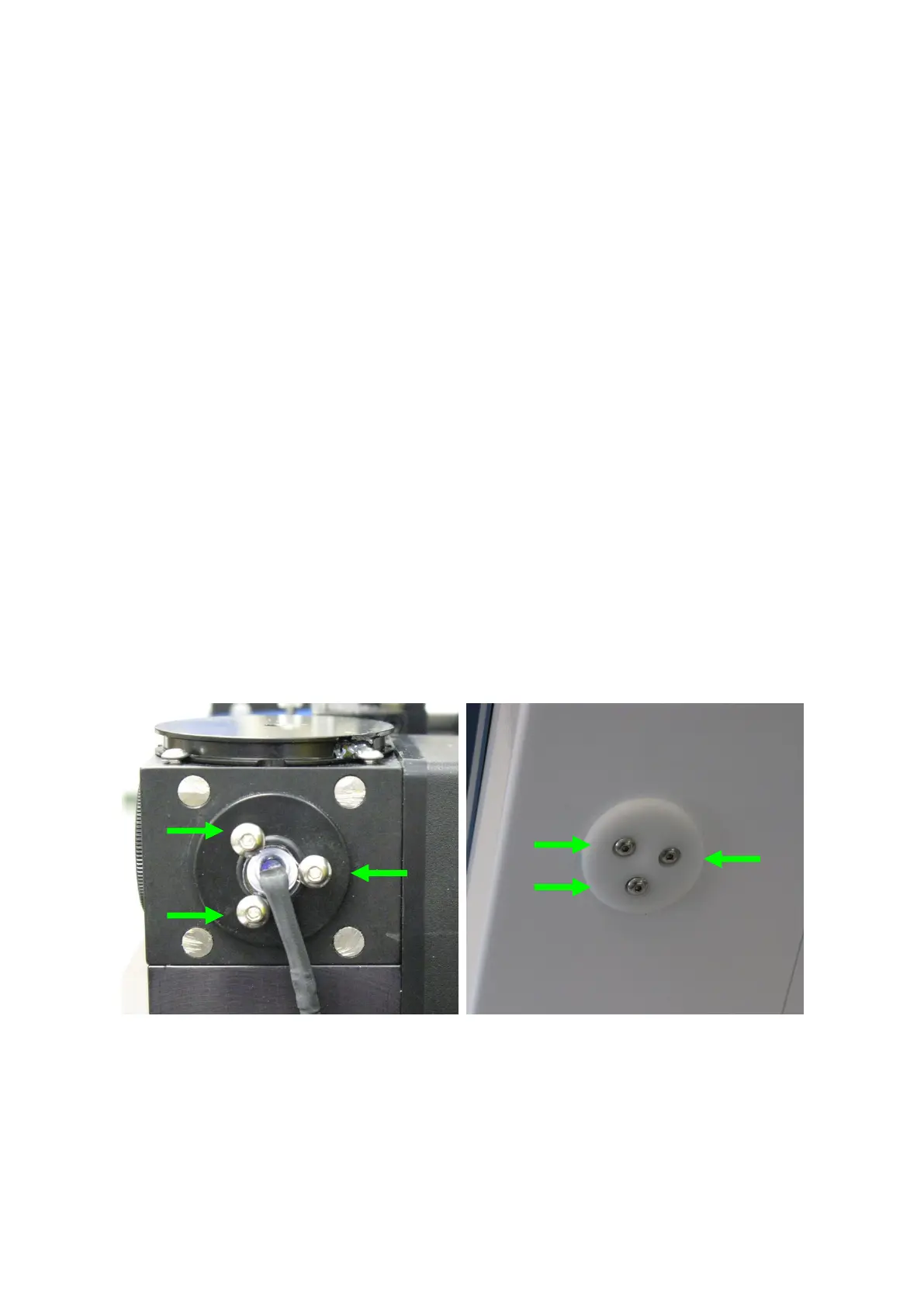
The second method to adjust the intensity of the light passing through the flow cell is a manual method.
To center the column of light within the field of view, one can manually re-position the LED flash by
adjusting the screws that hold it in place (see Figure 21). Using the supplied hex wrench, move each of
the three adjustment screws until the best illuminated images are achieved (see above for correct
Intensity values desired). This should be done with very small turns, never more than one full rotation
in either direction, to each screw in order to gauge the effects of each on the field of view illumination.
Once adjusted for one objective it may be necessary to re-adjust if a different objective is installed. In
summary, both the software and manual techniques can be used in combination to achieve the best
possible uniform field of view illumination and Intensity values.
Warning: Over-tightening LED Flash adjustment screws may cause damage, which would not be
covered by the Standard Factory Limited Warranty.
Figure 21. Location of the three LED Flash adjustment screws