TROUBLESHOOTING AND REPAIR
POWER SUPPLY
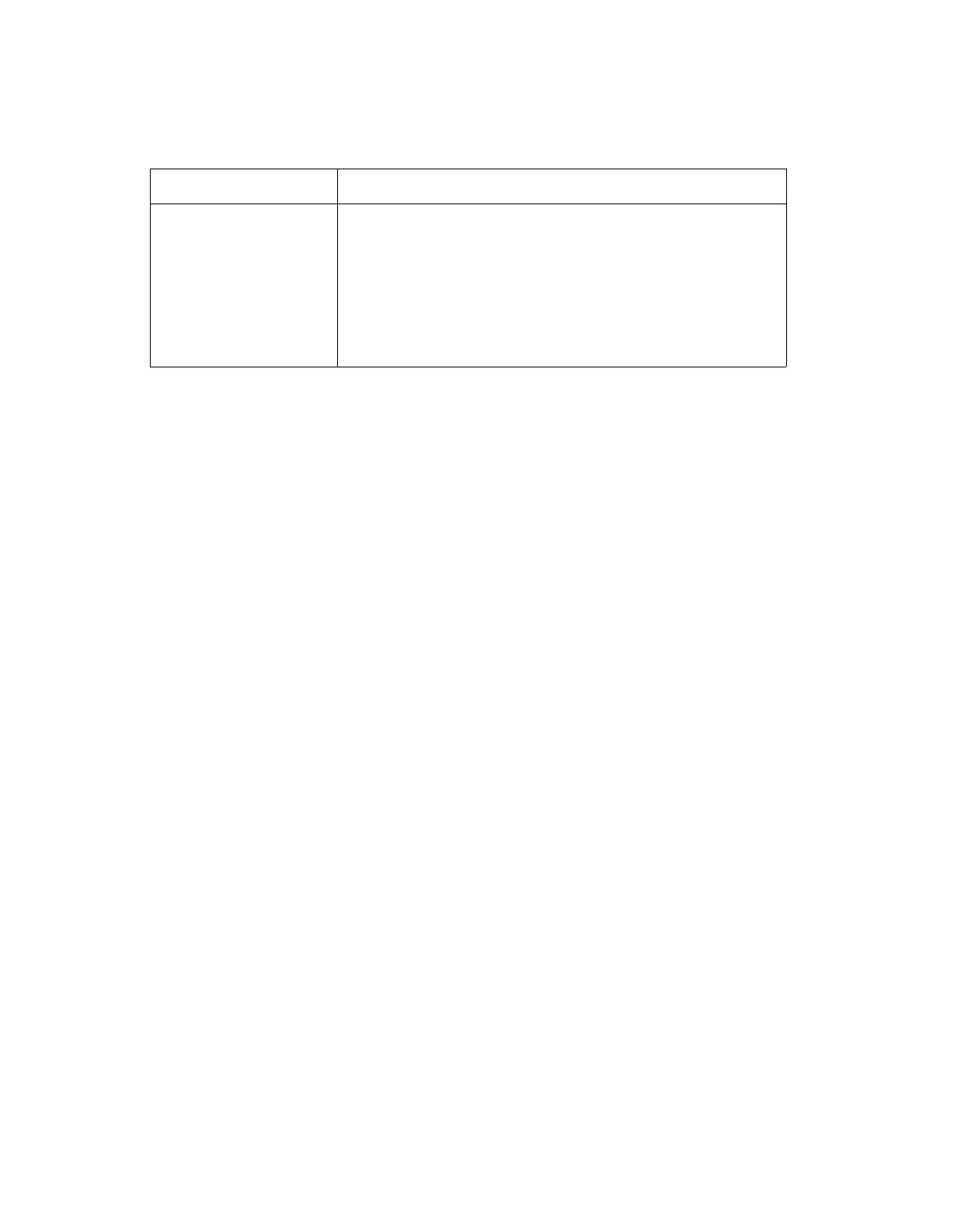
Table 6A-1. Supplies Provided by Power Supply Assembly
VOLTAGE
+24V DC
+23V DC
+5V DC
+15V
DC
-15V
DC
+37V DC
+30V DC
+6V AC
SUPPLY
Fan and Attenuator
Oven and Front Panel (Standby Supply)
Logic
Positive Analog
Negative Analog
Front Panel Display
High Voltage Analog
Display Filament Lines
The +24V, +23.4V, -5V, 37V and the +30V supplies use conventional three-terminal IC
regulators with internal current-limit and temperature protection.
The two highest power regulators, +5.1V and + 15V are of a very low noise, low ripple
design, that uses a high gain, low noise amplifier (U1), in a closed loop circuit with high
current Sense FET transistors (Q1 and Q2).
An over-current protection is provided to both the +5.V and + 15V supplies via the
Sense FET series-pass element's (Q1, Q2) internal current mirror, in conjunction with
the differential amplifiers (U2). When the load current set by R6 or R18 exceeds the the
zener diodes (CR5 or CR9) turn on, triggering the gate of the SCR (Q4). This in turn
sets pin 5 of comparator (U3) below its threshold voltage set by R19 and R22, which
sets the adjust terminal of the 37V regulator to -1.3V and turns off the 37V supply.
With the 37V supply off, the +30V and the +5V reference supplies are turned off, which
forces the +5.1V, +15V, and -15V to turn off. The 24V fan supply is not turned off on
this current limit. Q4 acts as a memory element, which requires resetting after it is
turned on. This can be done by turning off the front panel power switch.
The -15V supply is a low noise, low ripple design that utilizes a high gain, low noise
amplifier (U1) in a closed loop circuit with a conventional three-terminal IC regulator
(U6), which provides current-limit and temperature protection.
Both the +15V, and -15V regulated supplies have reverse-voltage protection diodes
(CR12 and CR14). The +5.1V supply has both reverse-voltage and over-voltage
protection (CR20).
The +5.1V, +15V, and -15V supplies are tracking and are adjustable via the +5V
reference supply adjustment (R41). It is recommended that R41 be adjusted for 5.10V
at
TP6.
A +6.2V supply is developed from the +37V supply through resistor R34 and zener
diode CR15. The +6.2V supply is then applied to the center tap of the 6V AC filament
supply. This provides the necessary grid bias for the front panel displays.
All regulators have their common reference terminals brought out to an external
ground point (P2) on the module section to reduce power supply ripple. Grounding all
GND lines and the GND SENSE line at the chassis is required to prevent damage to
the power supply circuitry.
6A-3