TROUBLESHOOTING AND REPAIR
FREQUENCY AND PHASE MODULATION
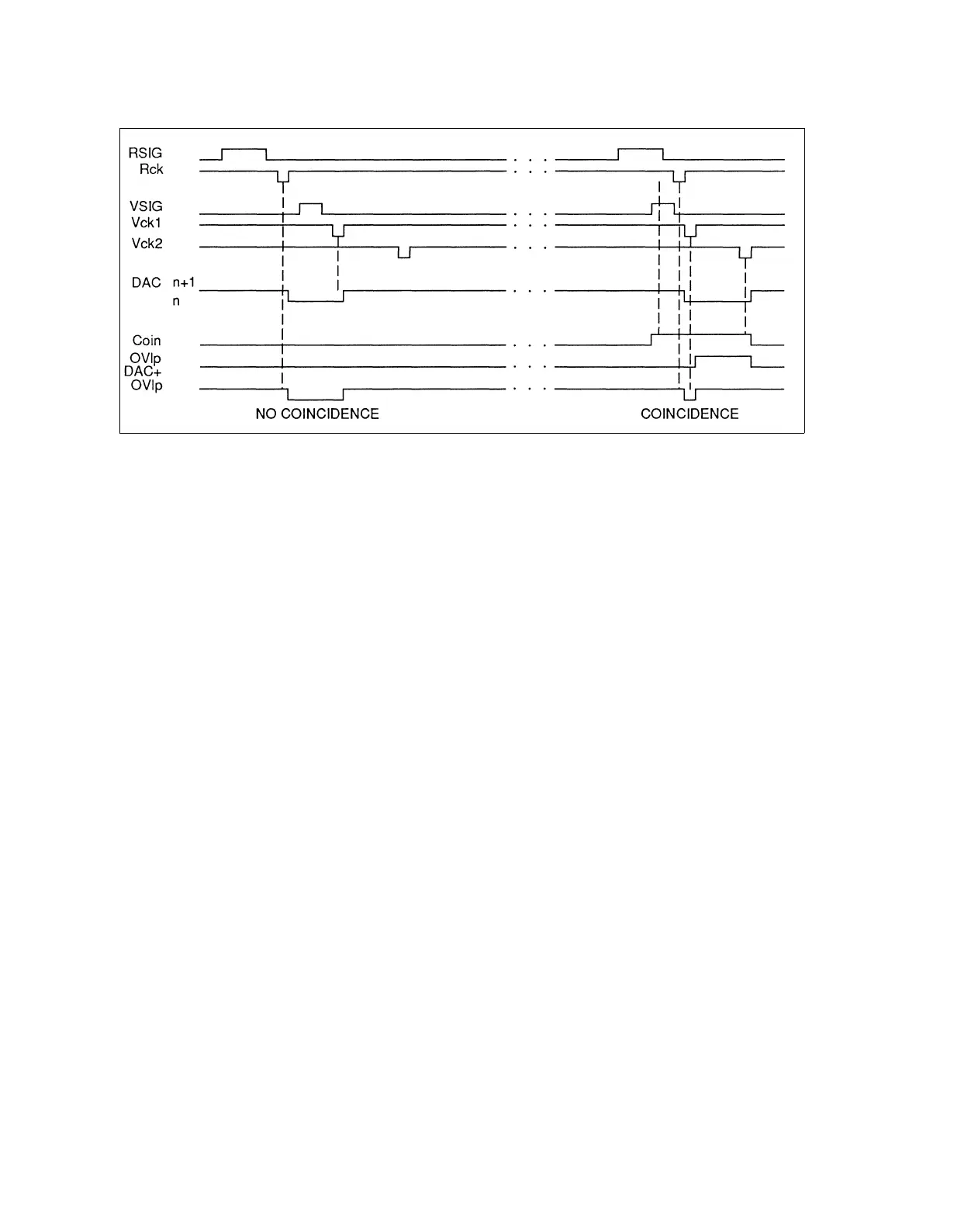
Figure 6E-3. Divider/Phase Detector Timing Diagram
The phase detectors operate at the phase detector reference frequency to produce
output signals that are related to the phase relationship of the FM-oscillator divider
combination to the phase of the reference frequency divider combination. One of the
phase detectors is programmed active. The output of the active phase detector is
selected with the analog switch, U24. This signal from the analog switch is amplified in
the integrating loop amplifier, U25. The result is filtered in the low-pass filter (L5-7)
and associated capacitors, to reduce the modulation of the 80-MHz FM oscillator by
the phase detector reference frequency. The filtered output drives the VCO-CONTROL
port of the 80-MHz FM oscillator to achieve phase lock and maintain correct center
frequency.
In the standard phase detector U21, one of two outputs is a pulse having a duty cycle
which is related to the phase relationship of the inputs. The other output becomes
active for wide phase deviation. These output signals drive the voltage level shifter
circuits, Q10, Q11, and the connected resistors, which drive diode (CR20-24) switched
resistor current sources. These currents pulses are passed through the analog switch,
p/o U24 to the loop amplifier, U25, virtual ground input. The average current, which is
proportional to the phase error between the FM oscillator and the reference, is
combined with a fixed current in the input, and the difference in current is amplified in
the integrating loop amplifier U25. The result achieves phase lock as indicated in the
previous paragraph.
For the wide deviation range N-PI phase detector, the reference and variable frequency
dividers alternately clock the up-down counter (U11) between two states with Rck and
Vck signals. Refer to Figure 6E-3. The up-down counter output four bits connect to the
four most significant bits of DAC U23, alternating the DAC between two states of its
total range of 16 states. This output is converted to a voltage output in an op amp, U50,
and into a current output with resistors R134 and R94 to drive through the analog
switch (U24) into the loop amplifier (U25). The alternating action of up down
continues smoothly as long as the up-down inputs do not coincide.
6E-5