Calibrators
Remote Control Interface (725 and 726)
15
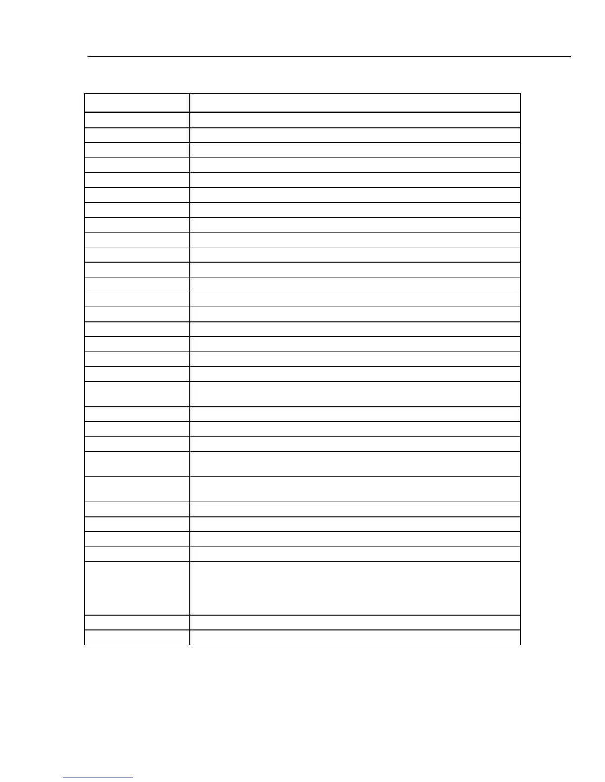
Table 3. Lower Display Remote Commands (725)
Remote Command Description
A mA measurement
a mA source
I mA 2W Sim
V Voltage measurement
v Voltage source
M mV measurement
m mV source
K kHz measurement
k kHz source
H Hz measurement
h Hz source
P CPM measurement
p CPM source
O Ohms measurement (default 2W)
o Select Ohms source
W 2-wire measurement (Ohms and RTDs)
X 3-wire measurement (Ohms and RTDs)
Y 4-wire measurement (Ohms and RTDs)
T Thermocouple measurement (default Type J). Use “S” command to select a
sensor type.
t Thermocouple source (default Type J). Use “S” command to select a sensor type
C Selects Centigrade ( T/C-RTD)
F Selects Fahrenheit ( T/C-RTD)
R RTD measurement mode (default Pt100 385). Use “S” command to select a
sensor type
r RTD measurement mode (default Pt100 385). Use “S” command to select sensor
type.
u Increment display source value
d Decrement display source value
< The < arrow key PC keyboard selects left arrow on 725
> The > arrow key PC keyboard selects right arrow on 725
0-9 Enter a source value using ASCII characters 0,1,2,...9,-,.terminated by <CR>
(carriage return)
-,. The 725 can receive a maximum of 10 characters prior to the carriage return.
<CR>
b Single Broadcast of most recent lower display value and units
) Single broadcast of most recent lower display value without header or units.

 Loading...


