724/725/726
Calibration Manual
38
Lower Display Ohms Source Tests
1. Press F ( R on the 726) on the UUT until Ω appears on the lower display. If
necessary, press M until SOURCE appears on the lower display.
2. Set the Fluke 8508A to measure 4-wire resistance.
3. Set the Fluke 8508A to 2 k range for 72x resistance < 400 Ω, to 20 kΩ range for
400 Ω or more.
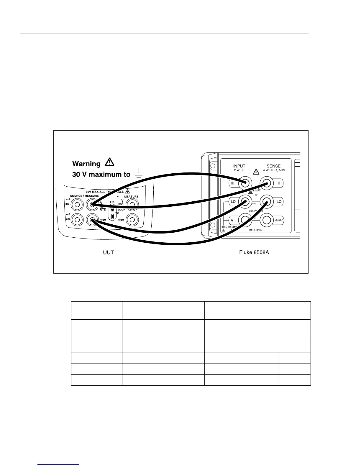
4. Make the connections shown in Figure 12.
5. Use the arrow keys on the UUT to set the UUT output to the resistance values in
Table 18 and verify that the Fluke 8508A readings are within the limits shown.
aal13f.eps
Figure 12. Lower Display Ohms Source Test Connections
Table 18. Lower Display Ohms Source Readings
UUT Settings
724/725
Fluke 8508A Readings
726
Fluke 8508A Readings
Range
15.0 Ω 14.9 Ω to 15.1 Ω 14.94775 Ω to 15.05225 Ω 2 kΩ
360.0 Ω 359.9 Ω to 360.1 Ω 359.896 Ω to 360.104 Ω 2 kΩ
500 Ω 499.5 Ω to 500.5 Ω 499.375 Ω to 500.625 Ω 20 kΩ
1500 Ω 1499.5 Ω to 1500.5 Ω 1499.275 Ω to 1500.725 Ω 20 kΩ
3200 Ω 3199.0 Ω to 3201.0 Ω - 20 kΩ
3800 Ω - 3798.93 Ω to 3807.01 Ω 20 kΩ
The performance tests for the 724 are now complete. Disconnect and secure all test
equipment.

 Loading...


