EasyManuals Logo

Fluke 724 Calibration Manual

Fluke 724
76 pages
To Next Page IconTo Next Page
To Previous Page IconTo Previous Page
Page #53 background imageLoading...
Page #53 background image
Calibrators
Calibration Adjustment
45
Cal mV Input
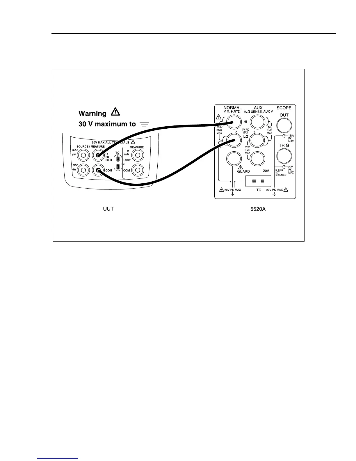
Connect the UUT as shown in Figure 17.
aal04.eps
Figure 17. mV Input Calibration Connections
From the Calibration Menu, type the number or letter for Cal mV Input. The PC displays:
Enter 0 mV - press space bar to continue
Set the Fluke 5520A to output 0.000 mV, let the output settle then press the space bar on
the PC. After a short while, the PC displays the following calibration constant and new
prompt:
Offset = -714
Enter 90.00 mV - press space bar to continue
Set the Fluke 5520A to output 90.000 mV, let the output settle, then press the space bar
on the PC. After a short while, the PC displays the following calibration constants and
new prompt:
diff = (Counts - Offset)
7513104 = 7512390 - -714
mV per count = 0.000012
-press space bar to continue
Press the space bar to return to the Calibration Menu.

Table of Contents

Other manuals for Fluke 724

Questions and Answers:

Question and Answer IconNeed help?

Do you have a question about the Fluke 724 and is the answer not in the manual?

Fluke 724 Specifications

General IconGeneral
Temperature Range-10°C to 55°C
Thermocouple TypesJ, K, T, E, R, S, B, L, U, N
Current Measurement0 to 24 mA
Operating Temperature-10°C to 55°C
FunctionProcess calibrator
RTD TypesPt100, Pt500, Pt1000
Voltage Measurement0 to 10 V
Loop Power24 V DC
DisplayDual Display
Power Supply4 AA batteries
Resolution0.1 °C
Storage Temperature-20 °C to 60 °C
Battery Life25 hours
Relative Humidity0 % to 90 %
Safety ComplianceCSA C22.2 No. 1010.1:1992

Related product manuals