EasyManuals Logo

Fluke 724 Calibration Manual

Fluke 724
76 pages
To Next Page IconTo Next Page
To Previous Page IconTo Previous Page
Page #41 background imageLoading...
Page #41 background image
Calibrators
Performance Tests
33
Lower Display 3-Wire RTD Measurement
1. Press F on the UUT (R on the 726) until appears on the lower display. If
necessary, use M to select the measure mode, and use X (R on the 726) to get to
the 3W mode. (MEASURE should also appear on the lower display.)
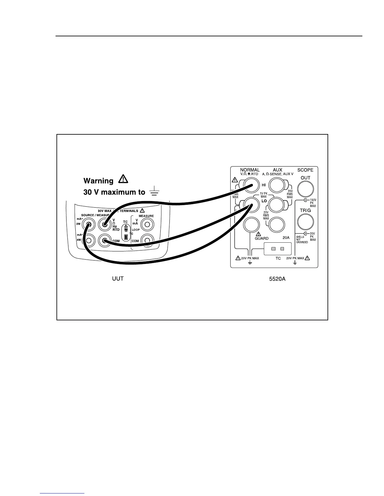
2. Set the 5520A to 2-wire output with 2-wire compensation off; then make the
connections shown in Figure 9.
3. Set the 5520A to source 350 and verify that the UUT resistance readings are within
the 349.80 to 350.2 .
4. Press STBY on the 5520A.
aal10f.eps
Figure 9. Lower Display 3-Wire Resistance Test Connections

Table of Contents

Other manuals for Fluke 724

Questions and Answers:

Question and Answer IconNeed help?

Do you have a question about the Fluke 724 and is the answer not in the manual?

Fluke 724 Specifications

General IconGeneral
Temperature Range-10°C to 55°C
Thermocouple TypesJ, K, T, E, R, S, B, L, U, N
Current Measurement0 to 24 mA
Operating Temperature-10°C to 55°C
FunctionProcess calibrator
RTD TypesPt100, Pt500, Pt1000
Voltage Measurement0 to 10 V
Loop Power24 V DC
DisplayDual Display
Power Supply4 AA batteries
Resolution0.1 °C
Storage Temperature-20 °C to 60 °C
Battery Life25 hours
Relative Humidity0 % to 90 %
Safety ComplianceCSA C22.2 No. 1010.1:1992

Related product manuals