EasyManuals Logo

Fluke 724 Calibration Manual

Fluke 724
76 pages
To Next Page IconTo Next Page
To Previous Page IconTo Previous Page
Page #42 background imageLoading...
Page #42 background image
724/725/726
Calibration Manual
34
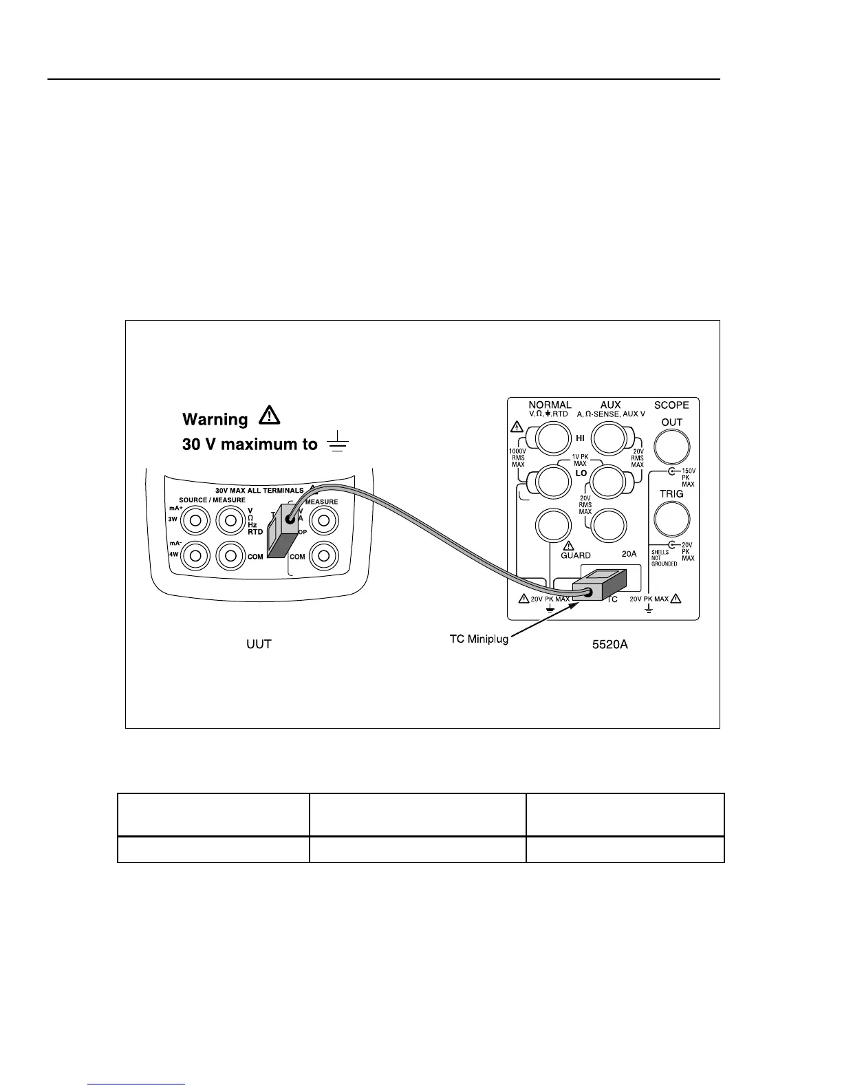
Lower Display Thermocouple Measurement Tests
1. Remove the test leads from the UUT terminals; then connect a Type-J thermocouple
lead between the TC jack on the UUT and the TC jack on the 5520A, as shown in
Figure 10.
2. Press T on the UUT until J appears on the lower display. If necessary, press D
(use the configuration menu on the 726) so the temperature is displayed in °C.
3. Set the 5520A to output the Type-J thermocouple voltages shown in Table 13 and
verify the UUT temperature readings are within the limits shown (values use the ITS-
90 curves).
4. Press STBY on the 5520A.
aal11f.eps
Figure 10. Lower Display Thermocouple Test Connections
Table 13. Type-J Thermocouple Readings
5520A Settings
(referenced to 0 °C)
724/725 UUT Readings 726 UUT Readings (CJC On)
0.0 °C (0.000 mV) -0.7 °C to +0.7 °C -0.4 °C to +0.4 °C

Table of Contents

Other manuals for Fluke 724

Questions and Answers:

Question and Answer IconNeed help?

Do you have a question about the Fluke 724 and is the answer not in the manual?

Fluke 724 Specifications

General IconGeneral
Temperature Range-10°C to 55°C
Thermocouple TypesJ, K, T, E, R, S, B, L, U, N
Current Measurement0 to 24 mA
Operating Temperature-10°C to 55°C
FunctionProcess calibrator
RTD TypesPt100, Pt500, Pt1000
Voltage Measurement0 to 10 V
Loop Power24 V DC
DisplayDual Display
Power Supply4 AA batteries
Resolution0.1 °C
Storage Temperature-20 °C to 60 °C
Battery Life25 hours
Relative Humidity0 % to 90 %
Safety ComplianceCSA C22.2 No. 1010.1:1992

Related product manuals