EasyManuals Logo

Fluke 724 Calibration Manual

Fluke 724
76 pages
To Next Page IconTo Next Page
To Previous Page IconTo Previous Page
Page #44 background imageLoading...
Page #44 background image
724/725/726
Calibration Manual
36
Lower Display mA Source Tests (725 and 726)
1. Press M on the UUT until SOURCE appears on the lower display; then press V
until mA appears on the lower display. If necessary, press M until SOURCE
appears on the lower display.
2. Set the Fluke 8508A to measure dc current.
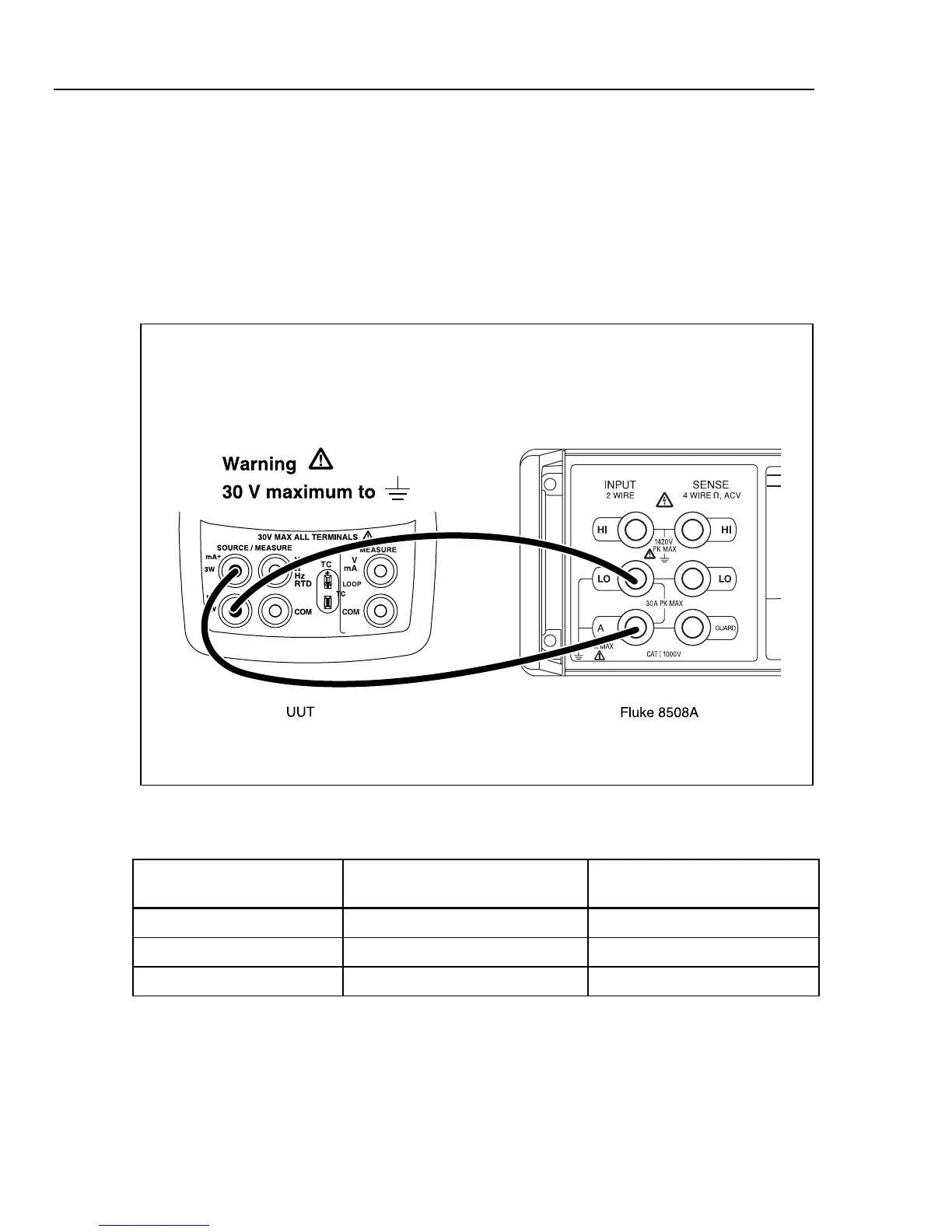
3. Connect the UUT and the Fluke 8508A as shown in Figure 11.
4. Use the arrow keys on the UUT to set the UUT to the currents in Table 15 and verify
that the Fluke 8508A readings are within the limits shown.
aal12f.eps
Figure 11. Lower Display mA Source Connections
Table 15. Lower Display mA Source Readings
UUT Outputs
724/725
Fluke 8508A Readings
726
Fluke 8508A Readings
4.000 mA 3.9972 mA to 4.0028 mA 3.9976 mA to 4.0024 mA
12.000 mA 11.9956 mA to 12.0044 mA 11.9968 mA to 12.0032 mA
24.000 mA 23.9932 mA to 24.0068 mA 23.9956 mA to 24.0044 mA

Table of Contents

Other manuals for Fluke 724

Questions and Answers:

Question and Answer IconNeed help?

Do you have a question about the Fluke 724 and is the answer not in the manual?

Fluke 724 Specifications

General IconGeneral
Temperature Range-10°C to 55°C
Thermocouple TypesJ, K, T, E, R, S, B, L, U, N
Current Measurement0 to 24 mA
Operating Temperature-10°C to 55°C
FunctionProcess calibrator
RTD TypesPt100, Pt500, Pt1000
Voltage Measurement0 to 10 V
Loop Power24 V DC
DisplayDual Display
Power Supply4 AA batteries
Resolution0.1 °C
Storage Temperature-20 °C to 60 °C
Battery Life25 hours
Relative Humidity0 % to 90 %
Safety ComplianceCSA C22.2 No. 1010.1:1992

Related product manuals